Http://www.elego.cc
134 / 137
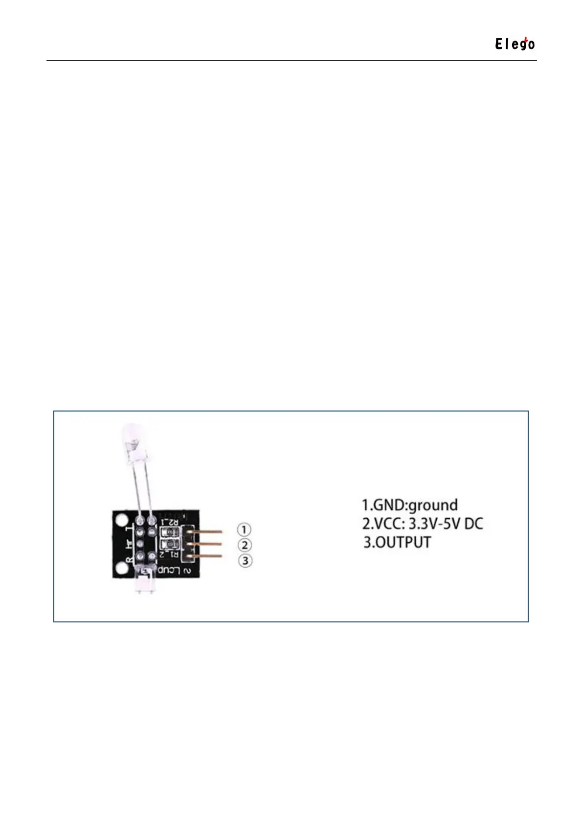
Lesson 26 HEARTBEAT MODULE
Overview
This project uses bright infrared (IR) LED and a phototransistor to detect the pulse of the
finger, a red LED flashes with each pulse. Pulse monitor works as follows: The LED is the light
side of the finger, and phototransistor on the other side of the finger, phototransistor used to
obtain the flux emitted, when the blood pressure pulse by the finger when the resistance of
the photo transistor will be slightly changed. The project's schematic circuit as shown, We
chose a very high resistance resistor R1, because most of the light through the finger is
absorbed, it is desirable that the phototransistor is sensitive enough. Resistance can be
selected by experiment to get the best results. The most important is to keep the shield stray
light into the phototransistor. For home lighting that is particularly important because the
lights at home mostly based 50HZor 60HZfluctuate, so faint heartbeat will add consider able
noise.
When running the program the measured values are printed. To get a real heartbeat from
this could be challenging.
Component Required:
(1) x Elego Uno R3
(1) x USB cable
(1) x Heartbeat module