1 2 3 4 5 6
DIPON
1 2 3 4 5 6
DIPON
1 2 3 4 5 6
DIPON
1 2 3 4 5 6
DIPON
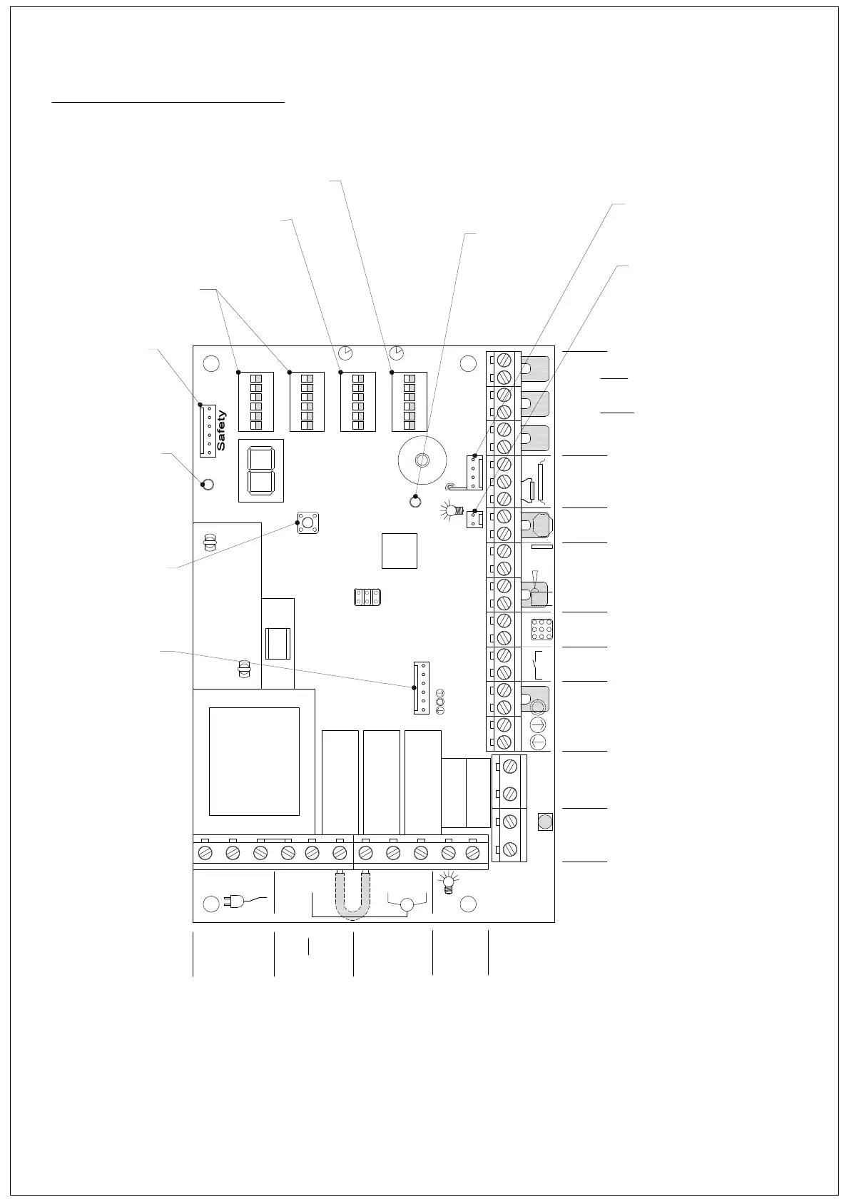
DIP4 DIP3 DIP2 DIP1
Prog II Prog I
RT CT
N L1 PE PE N L C
UP DWN
M
Light
Sig n al lig ht
re d
X3
OUT1
X4
UP DWN STOP C IMPULSE IN1 IN2 24VGNDNC
Ph oto
bea m
Emerg
Stop
GND SKS 12V
Sa fe ty ed ge
Prelim Close
Open
L im it Sw it ch es
X5
X6X7
RC
X8
T1
X3X2X1
Function
Settings
Run Timer
Settings
Closing Delay
Timer Setting
Power
Indicator
(GREEN)
Transmitter
Programming
Button
Independent (N/C) travel limit
switch - OPEN direction
Independent (N/C) travel limit
switch - CLOSE direction
Independent (N/C) pre-close
limit switch
Safety edge connection
resistive 8.2k or optical beam
Emergency Stop Button
(N/C)
Photocell
24v dc supply + N/C
connection
Keypad
Single Impulse Button
(sequential control)
OPEN-STOP-CLOSE-STOP
Push button control
independent direction open
and close + stop
circuit
Connector For
Plug in Radio Receiver
Connection For
Plug in 24v dc
Courtesy Light
Membrane
Push Button
connection
Pre-warning
Light or Red
Traffic Light
Green Traffic Light
230V Courtesy
Light
230v Motor Control
or Volt Free Output
230v Connection for Motor
(Not suitable for an Auxiliary
230v Mains Supply)
Motor
230v Mains Supply
Transmitter
Programming
Indicator
(RED)
Safety
Module
DC2 general connections
3