
R
Rachel PopeAug 4, 2025
What to do if Ellard Controller has no power?
- CcynthiabrooksAug 4, 2025
If your Ellard Controller is blank and has no power, you should check the mains fuse, the PCB fuse, and the mains power supply.
What to do if Ellard Controller has no power?
If your Ellard Controller is blank and has no power, you should check the mains fuse, the PCB fuse, and the mains power supply.
What to do if Ellard Controller radio control opens door but will not close?
If the Ellard Controller radio control opens the door but doesn't close it, you should: * Check the DIP switch position. * Check if the photocell is faulty or misaligned. * Check the wiring or for loose connections. * Check for a faulty safety edge.
What to do if safety edge is activated on Ellard Controller?
If the safety edge is activated on your Ellard Controller, you can try the following: * Check the DIP switch position. * Check the factory fitted resistor. * Check the wiring or for loose connections. * Replace the sensors.
What to do if the photocell is activated or open circuit on Ellard Controller?
If the photocell is activated or showing an open circuit on your Ellard Controller, you should: * Check the DIP switch position. * Check the photocell alignment. * Check the wiring or for loose connections. * Replace the photocell.
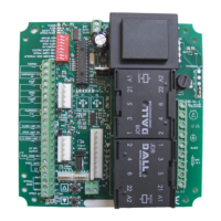
Overview of the safety module and DIP switch configuration for operation.
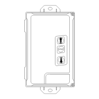
Connecting radio transmitters and membrane push buttons for control input.
Identification of key terminal blocks for power, motor, safety, and auxiliary connections.
Detailed instructions for wiring the 230V mains supply to the DC2 controller.
Instructions for connecting a 230V tube motor to the DC2 controller.
Wiring guide for volt-free connections to 'F', 'W', and 'SD' series operators.
Instructions for volt-free connections to 'JM' series operators and other controls.
Wiring diagram for connecting a remote push button control station.
Wiring for a remote impulse button with sequential control.
Instructions for connecting an N/C latching emergency stop button.
Wiring an 8.2k resistive safety edge, including DIP switch settings.
Connecting an optical safety edge and configuring DIP switches.
Wiring a pneumatic safety edge with an N/C air switch.
Connecting a reflective photocell and setting DIP switches.
Configuration for pre-warning light function and DIP switch settings.
Wiring and DIP switch settings for the 230V courtesy light.
Wiring and DIP switch settings for red/green traffic light indicators.
Procedure for programming up to 20 radio transmitters into the DC2 controller.
Steps to delete programmed radio transmitters from the DC2 controller.
Configuration of motor run timer settings using DIP switch 'RT'.
Adjustment of closing delay timer settings using DIP switch 'CT'.
Common faults, their display indicators, and troubleshooting checks.
Specifications including model, supply voltage, frequency, and protection class.
| Brand | Ellard |
|---|---|
| Model | DC2 |
| Category | Controller |
| Language | English |