2 Installation
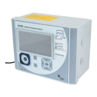
gas-net F1
Page 2-2
device. However, these terminals have to comply in part with the Ex-regulations
and must possibly also be sealable.
2.2.1 Power Supply and Earthing
Operate the gas-net F1 device with a nominal voltage of 24 V DC.
The connection of 24 V is implemented via the terminals
+ and – on the back of
the device and must be protected externally against short circuits with 1 A. The
internal device protection is guaranteed by a self-resetting overcurrent protector.
Connect the protective earth to PE of the power supply socket for equipotential
bonding.
2.2.2 Process Boards
The process board equipment of a gas-net F1 depends on the tasks the device
is supposed to accomplish. Generally, the maximum number of boards depends
on the mounting width of the device housing: Housings with a mounting width of
1/3 accommodate up to four process boards whereas housings with a mounting
width of 1/2 mounting accommodate up to seven process boards.
Altogether, only up to four boards of the types EXMFE5, EXDE6 and
MSER2 can be employed in one device.
2.2.2.1 EXMFE5 Input Board
Important Note: The EXMFE5 input board is approved as an associated
electrical apparatus of category ib according to DIN EN 50020 with intrinsically
safe circuits. This is why sensors and signal transmitters located in hazardous
areas (e.g. zone 1) can be connected to this board. A mixed operation
of intrinsically safe and non-intrinsically safe circuits is not
permissible
for such an input board.
To the first three channels of an explosion-proof EXMFE5 input board,
intrinsically safe pulsers in NAMUR technique can be connected. The
channels of the EXMFE5 can also be used as message input
channels. Alternatively, it is also possible to connect an encoder
totalizer to the first one of these input channels for a digital
transmission of original meter readings.
Connect the signals for channels 1 to 3 to terminals Z1+, Z1-, Z2+, Z2-,
and Z3+, Z3-.
 Loading...