Installation 2
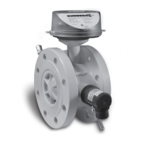
gas-net F1
Page 2-3
The inputs are intrinsically safe. Use shielded cables for a better interference
suppression. The maximum cable length is 100 m at a cross section of
1.5 square mm. If the cables are longer, you have to ensure that the lines are
installed separately from other conducting lines to avoid interferences.
Moreover, each EXMFE5 board has one intrinsically safe temperature sensor
input in 4-wire technique to be connected to terminals I+, U+, U- and I-
according to the Pt100 Specification.
The board is also equipped with an intrinsically safe input for measuring sensors
(e.g. a pressure sensor) in 4..20 mA-two wire-technique (terminals P+ and P-).
This fifth channel of the EXMFE5 input board can also be used for the parallel
connection of up to 4 measuring sensors using a HART interface (multi-drop
procedure).
5
For the sensors, only the HART polling addresses from 1 to 4 are
allowed; make sure that the address assignment is unambiguous and
corresponds to the assignment in the parameterization of the gas-net device.
Important Note: In general, each modification of the wiring is only permitted
after the supply has been disconnected. This means in particular in case of
HART sensors that the HART polling addresses must be adjusted individually in
the sensors before connecting them together to the corresponding input channel
at the gas-net device in de-energized conditions. When the device starts up
again afterwards, all connected HART sensors are polled once for the device to
find out the current polling addresses.
If you would change the polling addresses later, the gas-net device would not be
able to identify the individual sensors correctly.
The device supplies the measuring sensors with power. For this, shielded
cables must be used with the shielding being fitted only at the device but not at
the sensor. If the line cross section is 1.5 square mm, the line should not be
longer than 100 m; otherwise, it must be guaranteed that the lines are installed
separately from other conducting lines to avoid interferences.
The cable shielding for all transmitter lines is placed on the SH terminal at the
EXMFE5 input board.
5
Please consult Elster if you would like to connect sensors via HART protocol and the
cable is longer than 50 m.
 Loading...