2 Installation
gas-net F1
Page 2-4
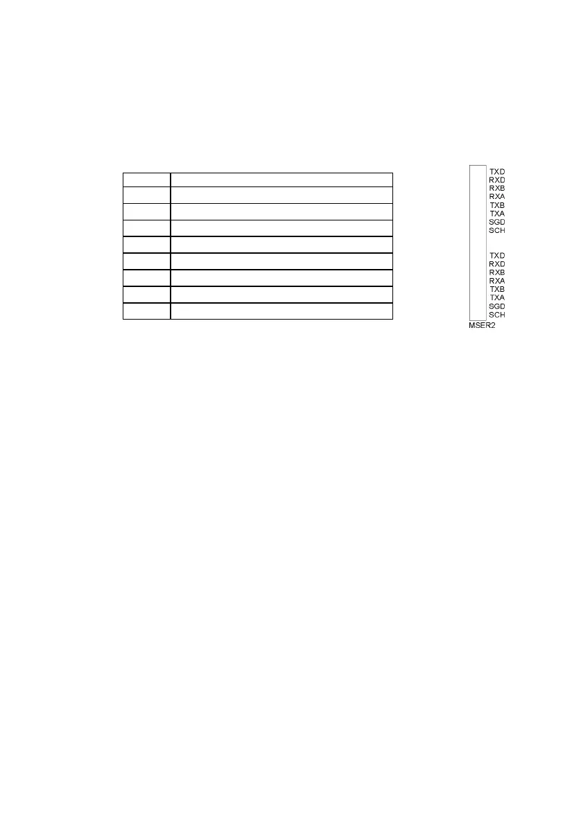
2.2.2.2 MSER2 Serial Process Board
The MSER2 serial process board provides two interfaces supporting V24
(RS232) as well as RS422 and RS485. The table below shows the assignment
of the individual pins:
Signal Assignment
TXD RS232: Transmitted data
RXD RS232: Received data
RXB RS422/RS485: Received data (B)
RXA RS422/RS485: Received data (A)
TXB RS422/RS485: Transmitted data (B)
TXA RS422/RS485: Transmitted data (A)
SGD Signal ground
SCH Shield
An MSER2 board must always be installed in the device if an ultrasonic gas flow
meter (type Q.Sonic or FLOWSIC) is connected via RS485. Another application
of an MSER2 board is the connection of a host computer via RK512/3964R or
MODBUS protocol or the connection of a GPS receiver for the time
synchronization.
Notes:
When RS422 and RS485 are used, a terminating resistor of 120 ohms may
be required in the receiver between RXB and RXA, depending on the cable
length.
In case of RS485, you have to externally connect RXB to TXB and RXA to
TXA.
Please pay attention to the specification of the individual protocols. For
instance, there are protocols that render a connection via RS485 impossible
(e.g. in case of RK512).
 Loading...