Installation 2
gas-net F1
Page 2-5
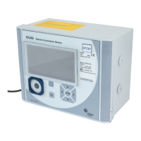
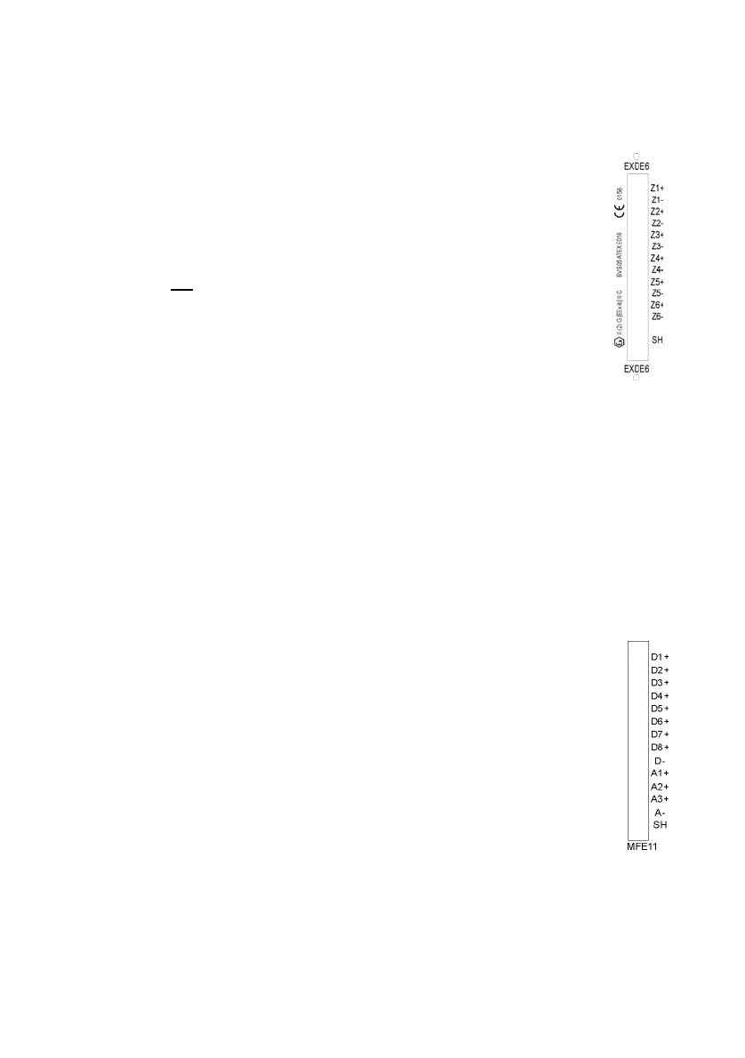
2.2.2.3 EXDE6 Input Board
Important note: The EXDE6 input board is approved as an
associated electrical apparatus of category ib according to DIN EN
50020 with intrinsically safe circuits. This is why signal transmitters
located in hazardous areas (e.g. zone 1) can be connected to this
board. A mixed operation of intrinsically safe and non-intrinsically safe
circuits is not
permissible for such an input board.
To the channels of an explosion-proof EXDE6 input board, intrinsically
safe pulsers in NAMUR technique can be connected, but the channels
may also be used as message input channels. Alternatively, it is also
possible to connect an encoder totalizer to the first one of these input
channels for the digital transmission of original meter readings.
Connect the signals for channels 1 to 6 to terminals Z1+, Z1- to Z6+, Z6-.
The inputs are intrinsically safe. Use shielded cables for a better interference
suppression. The maximum cable length is 100 m at a cross section of
1.5 square mm. If the cables are longer, you have to ensure that the lines are
installed separately from other conducting lines to avoid interferences.
The cable shielding for all transmitter lines is placed on the SH terminal at the
EXDE6 input board.
2.2.2.4 MFE11 Input Board
The multi-functional MFE11 input board is equipped with eight digital
message inputs 0/24 V DC. However, it is also possible to use these
channels as pulse inputs with a maximum input frequency of 25 Hz.
Connect the inputs at terminals D1+ to D8+ with the common ground
D-.
In addition, the MFE11 input board provides three analog inputs for
the connection of measuring sensors with 0/4 to 20 mA output signals.
Connect the inputs via terminals A1+ / A2+ / A3+ with the common
ground A-.
The analog inputs of the MFE11 board are electrically isolated from
the digital inputs. Besides, all channels are electrically isolated from the rest of
the system. Connect the cable shielding for the inputs to the SH terminal.
 Loading...