Static Transfer Switch
STS207
User Manual
Page 10 (28)
ELTEK VALERE DEUTSCHLAND ©2009 UM_STS207_WEB_E_R1.4
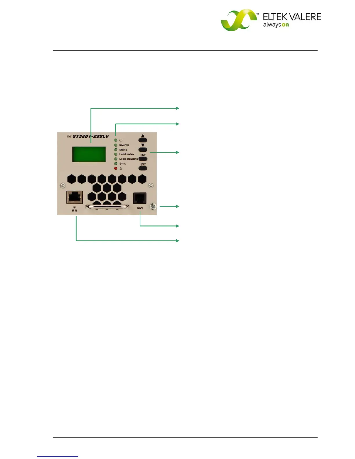
3.3 Front view: operating elements, indicators
Figure 3. Front view
For more information about the operating elements, LED indicators, LC-Display and front connectors,
see the following sections.
The STS207 is equipped with:
One LC-Display (4 x 16 characters)
Seven LED indicators: STANDBY, INVERTER, MAINS,
LOAD ON INVERTER, LOAD ON MAINS, SYNC, ALARM
(Collective failure)
Four adjustment keys: Up, Down, ENT, ESC
One captive screw is used for each module to
secure it to the sub rack (component of the module).
CAN connector (RJ11)
Ethernet connector 10/100MB (RJ45)
 Loading...