Static Transfer Switch
STS207
User Manual
Page 13 (28)
ELTEK VALERE DEUTSCHLAND ©2009 UM_STS207_WEB_E_R1.4
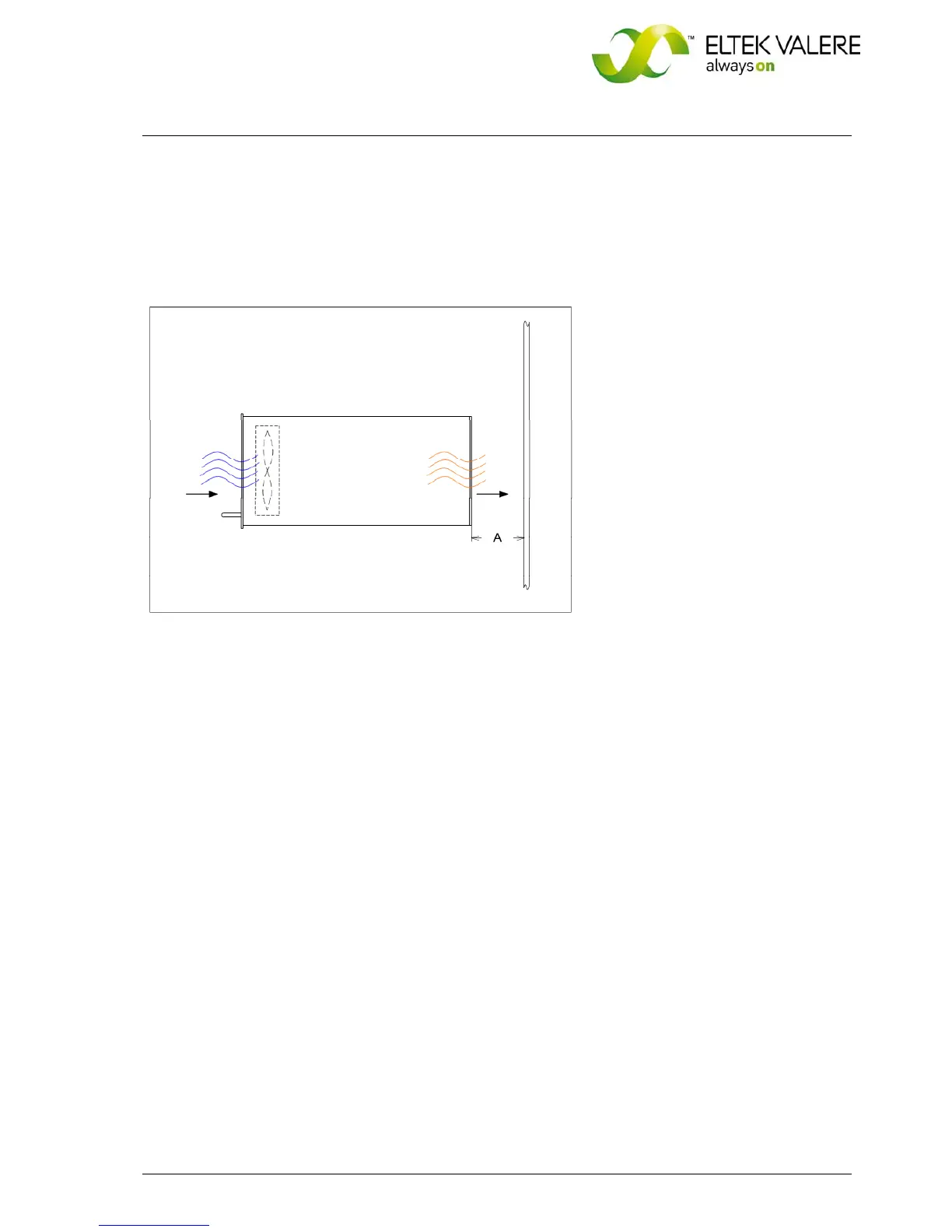
3.5 Cooling/Air flow direction
The unit is cooled by an internal fan. The airflow is from the front to rear side. The fan is monitored and
speed controlled dependent on module temperature. To provide sufficient air flow, a minimum space
(see item “A” in figure 7) of 50 mm is required between the unit and the rear cabinet wall as well as an
unobstructed supply of air to the front of the module.
Figure 7. Module air flow
3.6 Communication interfaces
3.6.1 CAN-Bus
The STS207 is equipped with a serial data interface in accordance with the Controller Area Network
(CAN) specification. The CAN-Bus connection is integrated in the rear side connector and an additional
one is located at the front panel.
The communication of the STS207 with the connected inverters and a possibly implemented UPC3 DC
controller unit takes place via CAN-Bus.
The following information is available via CAN:
Status information of the STS207:
Availability of the connected inverters
Availability of the substitute mains
Load on mains/inverter
Synchronization
Vbatt </>
Vout </>
Iout >
Output current of the STS
Battery voltage connected to the STS
Inverter and mains voltage
Inverter and mains frequency
STS module temperature
 Loading...