Static Transfer Switch
STS207
User Manual
Page 12 (28)
ELTEK VALERE DEUTSCHLAND ©2009 UM_STS207_WEB_E_R1.4
3.4.2 Pin assignment of the front side CAN-Bus connector (RJ11):
Pin Signals CAN Designation
1 CAN_V+ DC-Supply +8...15V
2 CAN_V+ DC-Supply +8...15V
3 CAN_H Signal (high)
4 CAN_L Signal (low)
5 CAN_V- DC-Supply Ground
6 CAN_V- DC-Supply Ground
1
6
Figure 5. Front side CAN-Bus connector
(socket outlet RJ11, 6-pole)
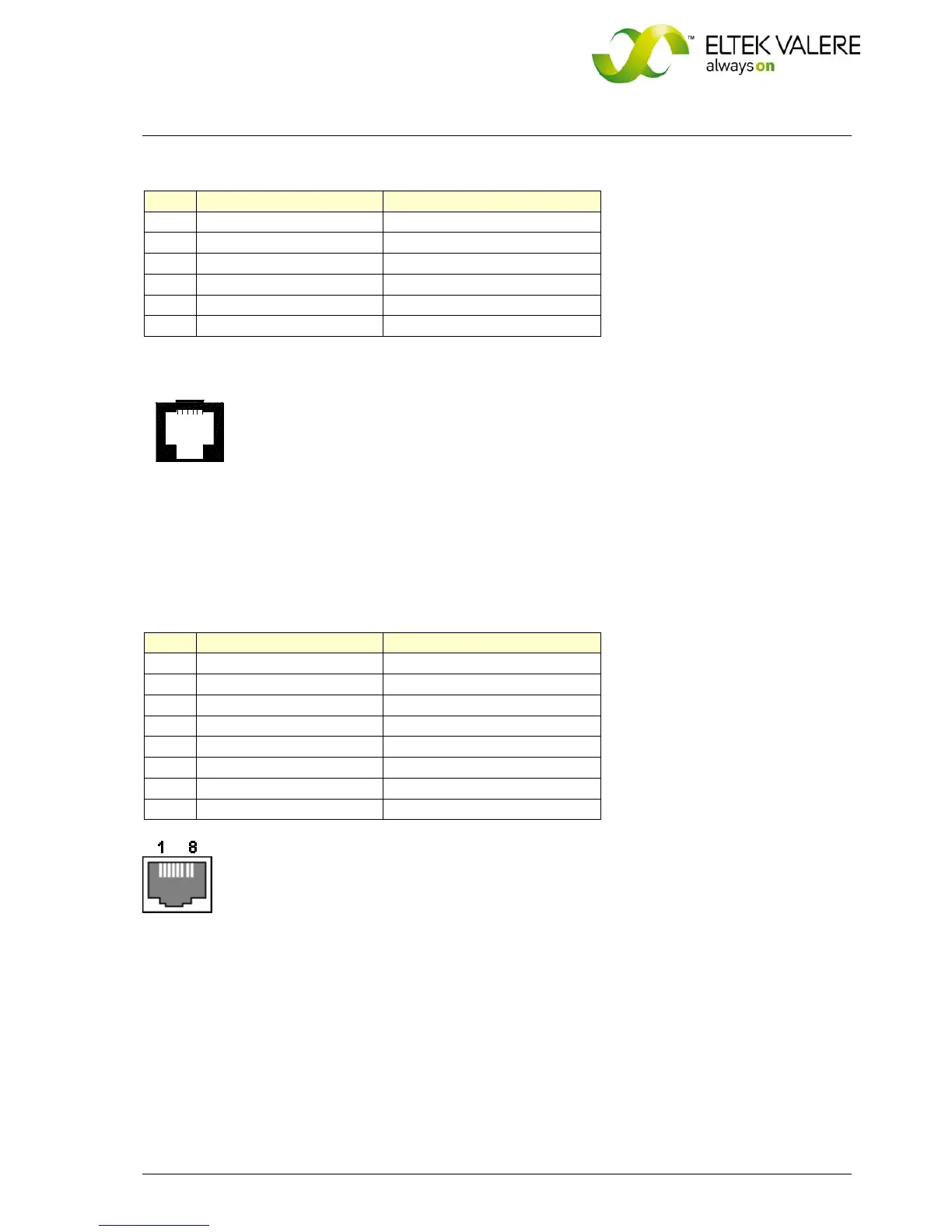
3.4.3 Pin assignment of the front side Ethernet connector (RJ45):
Pin Name Designation
1 TX+ Tranceive Data +
2 TX- Tranceive Data -
3 RX+ Receive Data +
4 n/c Not used
5 n/c Not used
6 RX- Receive Data -
7 n/c Not used
8 n/c Not used
Figure 6. Front side Ethernet connector
(socket outlet RJ45, 8-pole)
 Loading...