Static Transfer Switch
STS207
User Manual
Page 11 (28)
ELTEK VALERE DEUTSCHLAND ©2009 UM_STS207_WEB_E_R1.4
3.4 Electrical connections
The STS207 is equipped with:
1 rear side connector for: AC input 1 (inverter), AC input 2 (mains), AC output and signalling
1 front side connector RJ11 (additional CAN-Bus connector)
1 front side connector RJ45 (Ethernet 10/100MB)
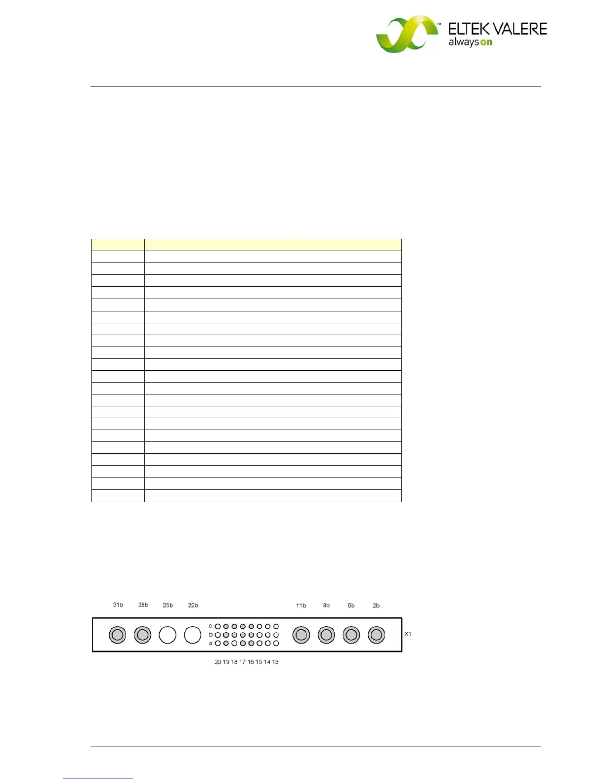
3.4.1 Pin assignment of the rear side connector:
Pin Designation
2b AC-Input 1 (Inverter)/Phase L1
5b STS-Output / Phase L1
8b AC-Input 2 (Mains)/Phase L1
11b Common Neutral Conductor
16a
CAN_L Signal ( low )
17a CAN_V+ DC-Supply +8…15V
18a -
19a Synchronization / SYNC - STAT 2
20a -
16b CAN_V- DC-Supply GND
17b CAN_H Signal ( high )
18b Synchronization / SYNC - STAT 1
19b Synchronization / SYNC - SIG 2
20b -
16c Alarm relay output, NO
17c Alarm relay output, COM
18c Synchronization / SYNC - GND
19c Synchronization / SYNC - SIG 1
20c -
28b
+Vi (DC-Power Supply* )
31b
-Vi (DC-Power Supply* )
* STS207HV: Vi = 91.8-275V
DC
STS207LV: Vi = 38-75VDC
STS207LV: Vi = 19-45V
DC
Figure 4. Rear side connector (shown from the rear side of the module)
 Loading...