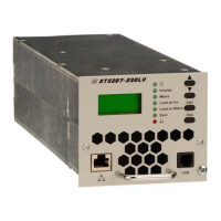
Static Transfer Switch
STS207
User Manual
Page 5 (28)
ELTEK VALERE DEUTSCHLAND ©2009 UM_STS207_WEB_E_R1.4
Index of Figures
Figure 1. Block diagram “Example of use”
....................................................................................................................7
Figure 2. AC Rack ACR INV222-6.75 ..............................................................................................................................9
Figure 3. Front view......................................................................................................................................................... 10
Figure 4. Rear side connector....................................................................................................................................... 11
Figure 5. Front side CAN-Bus connector.................................................................................................................... 12
Figure 6. Front side Ethernet connector.................................................................................................................... 12
Figure 7. Module air flow ................................................................................................................................................ 13
Figure 8. Sample screenshot ........................................................................................................................................ 14
Figure 9. LC-Display: Indication of measured values .............................................................................................. 17
Figure 10. Structure of the customer menu............................................................................................................. 19
Figure 11. Continuation of the customer menu....................................................................................................... 20
Figure 12. Display “Alarm Messages”.......................................................................................................................... 21
Figure 13. Module dimensions...................................................................................................................................... 25

 Loading...