BA-en-3018-2006_KNH18 11
3. Installation and Assembly
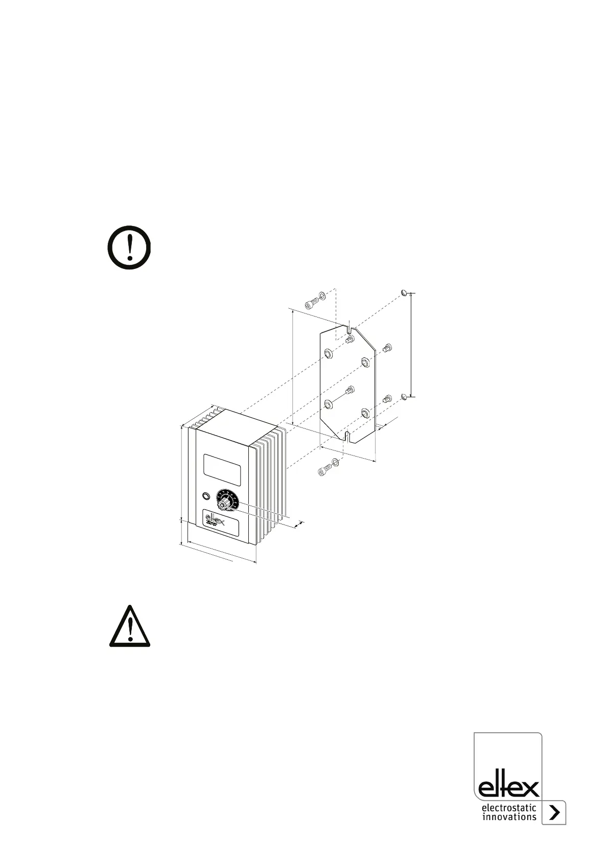
3.1 Assembly of the high voltage generator
The unit is designed either for wall assembly or table mounting. Attach the
unit using the assembly/mounting brackets supplied with the unit (see fig-
ure). The bulging of the holes in the support plate must point in the direc-
tion of the generator. When mounting the unit make sure that the
operating elements and the connector terminals remain accessible and
that control of the unit is not impaired.
The site of installation must be dry and free of dust, if possible. Air circula-
tion above the cooling ribs must not be obstructed.
3.2 Grounding
Before putting the high voltage generator into operation make sure that
the appliance is permantly grounded via the ground terminal (3, Fig. 1).
The ground cable should have a minimum cross section of 1.5 mm
2
and
be connected to ground along the shortest possible routing via a conduc-
tive cable. A cross section of 2.5 mm
2
is required for cable lengths
exceeding 0.5 meters
Fig. 2:
Installation of the
high voltage
generator with
supporting plate
Z00181y
330
>100
212
128
170
M8
M8
M6
M6
386
2,5
410
27
 Loading...