NTU-52V/VC. User manual (user)
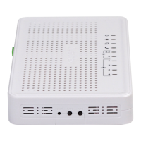
Table 4 – Description of the connectors and controls on the rear panel
# Rear panel element Description
1 On/Off Power button
2 12V Power adapter connector
3 F A functional key that reboots the device and resets it to factory settings
4 TV RF port for connecting a coaxial cable
5 LAN 10/100 RJ-45 port for network devices connection (Ethernet/Fast Ethernet)
6 LAN 10/100/1000 RJ-45 port for network devices connection (Gigabit Ethernet)
7 Phone RJ-11 connector for analogue phone connection
8 PON SC port (socket) for PON with GPON interface
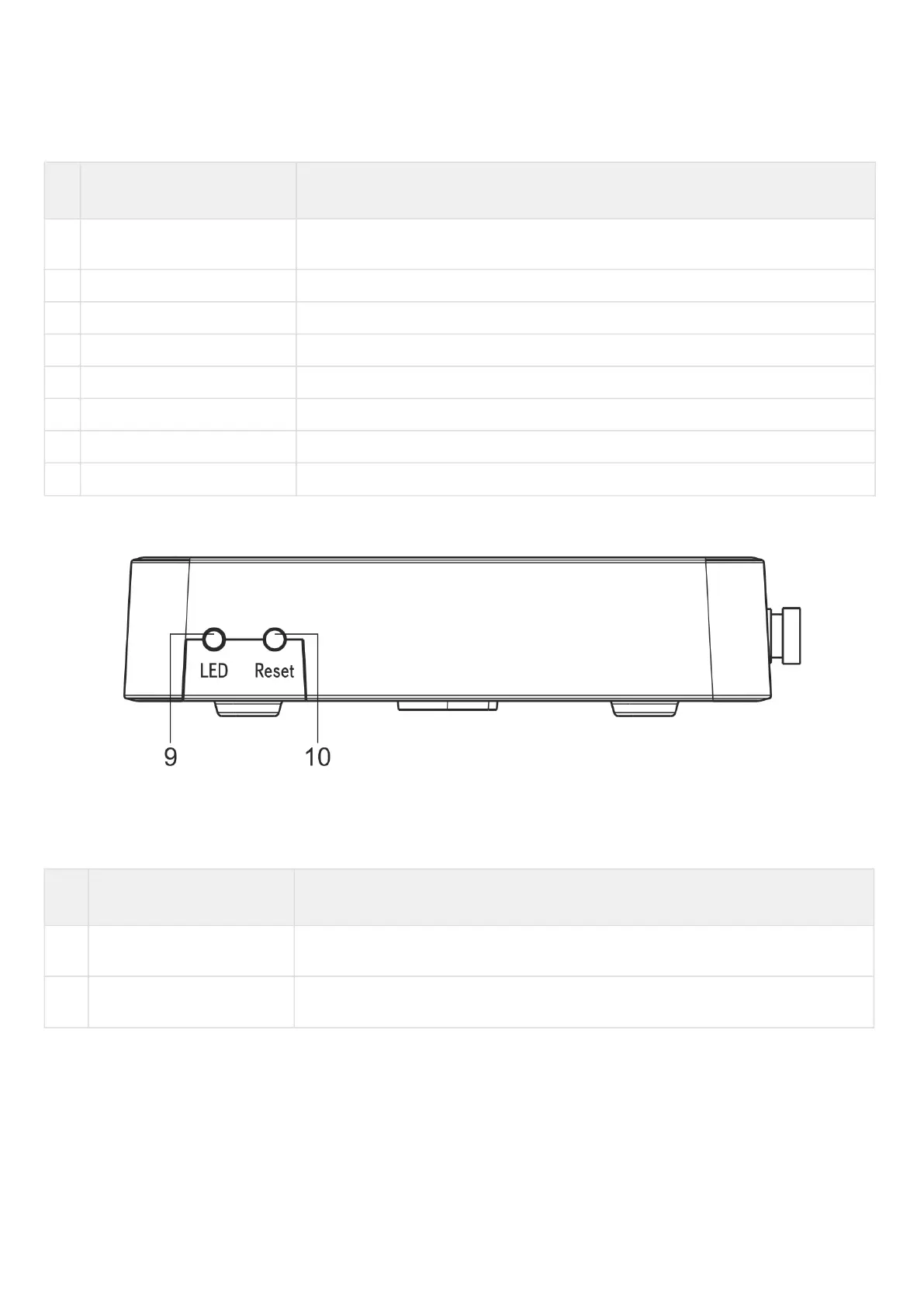
The side panel layout of the NTU-52V is depicted in figure below.
Figure 4— NTU-52V side panel layout
See Table 5 for detailed information about buttons located on the side panel of the device.
Table 5 – Description of the side panel LED indicators
# Side panel element Description
1 LED LED on/off button
2 Reset/restore A functional key that reboots the device and resets it to factory settings
 Loading...