Interpreting LED activity
35
Operating the DS-5300B
Interpreting LED activity
System activity and status can be determined through the activity of
the LEDs on the switch.
There are three possible LED states:
◆ No light
◆ Steady light
◆ Flashing light
The lights are in one of the following colors:
◆ Green
◆ Amber
The status LEDs may display amber or flash during boot, POST, or
other diagnostic tests. This is normal; it does not indicate a problem
unless the LEDs do not indicate a healthy state after all boot processes
and diagnostic tests are complete.
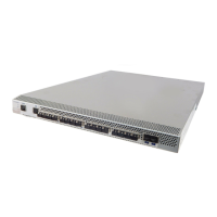
LEDs on the port side of the switch
The port side of the switch has the following LEDs:
◆ One system status LED (above) on the left side.
◆ One power status LED (below) on the left side.
◆ Two Ethernet Port LEDs
◆ One port status LED for each port on the switch. These LEDs are
arrayed below each pair of Fibre Channel ports. The port LEDs
are located in the array in the same relative positions as the ports.
Figure 3 on page 36 shows the port side of the DS-5300B.
 Loading...