Do you have a question about the EMC DS-4900B and is the answer not in the manual?
Provides a general description of the DS-4900B, its features, and capabilities.
Explains the licensing mechanism for enabling additional ports on the DS-4900B switch.
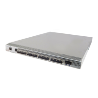
Details the physical layout and components found on the port side of the DS-4900B switch.
Describes the physical layout and components on the nonport side, including power supplies and fans.
Outlines the methods and tools available for managing the DS-4900B switch's operations.
Lists features pre-installed and optional software features that can be enabled via licenses.
Explains the concept of 8-port trunk groups and user ports per ASIC for the DS-4900B.
Details the capabilities and limitations for trunking connections over extended distances.
Specifies the maximum number of long distance ports supported based on speed and distance.
Covers essential safety precautions and environmental requirements for installing the DS-4900B.
Lists all the hardware and accessory items that come with the DS-4900B switch.
Provides instructions for configuring the DS-4900B as a standalone device outside of a rack.
Details the process and options for mounting the DS-4900B within a standard EIA rack cabinet.
Outlines the step-by-step procedure for the initial configuration and connection of the DS-4900B.
Offers best practices and guidelines for organizing and managing cables connected to the switch.
Explains how to understand the status of the switch through its various LED indicators.
Details the system, power, Ethernet, and port status LEDs located on the port side.
Describes the power supply and fan status LEDs found on the nonport side of the switch.
Guides users on how to interpret the results of the Power-On Self-Test (POST) for hardware status.
Covers diagnostic tests and the replacement of field-replaceable units (FRUs) for system maintenance.
Provides instructions on how to safely shut down and power off the DS-4900B switch.
Details the procedure for replacing the fan assemblies in the DS-4900B switch.
Specifies the estimated time needed to perform a fan assembly replacement.
Lists the necessary tools and parts for replacing a fan assembly.
Step-by-step instructions for removing and installing a new fan assembly.
Outlines the procedure for replacing the power supply units in the DS-4900B switch.
Indicates the estimated time to complete a power supply replacement.
Lists the tools and parts needed for replacing a power supply.
Step-by-step instructions for removing and installing a new power supply unit.
Describes the main hardware components that make up the DS-4900B switch.
Provides the physical measurements and weight specifications for the DS-4900B.
Details the electrical, thermal, and cabinet requirements for the installation environment.
Lists the technical specifications related to the power supply units of the DS-4900B.
Specifies the acceptable ambient temperature, humidity, and altitude ranges for operation.
Covers general technical details including EMC compliance, system architecture, and protocols.
Provides information on the operational distances for data transmission based on port speed and cable type.
Details the types and sizes of memory devices used in the DS-4900B.
Describes the capabilities and compatibility of the Fibre Channel ports on the DS-4900B.
Details the specifications and pinouts for the serial console port on the DS-4900B.
Explains the Power-On Self-Test (POST) process and the switch boot sequence.
Lists various regulatory compliance statements and standards applicable to the DS-4900B.
| Switch Architecture | Non-blocking |
|---|---|
| Power over Ethernet | No |
| Switching Capacity | 768 Gbps |
| Port Speed | 1/2/4 Gbps |
| Ports | 48 |
| Management | CLI |
| VLAN Support | Yes |
| Operating Temperature | 0°C to 40°C (32°F to 104°F) |
| Storage Temperature | -40°F to 158°F (-40°C to 70°C) |
| Humidity | 10% to 85% noncondensing |
| Frequency | 50/60 Hz |