EMC® VNX5300™ Hardware Information Guide
36
EMC® VNX5300™ Hardware Information Guide
Note: If you received the Block and File VNX5300 platform already installed in a cabinet rack
with all of the Block and File VNX5300 platform components, all the cabling has already been
installed.
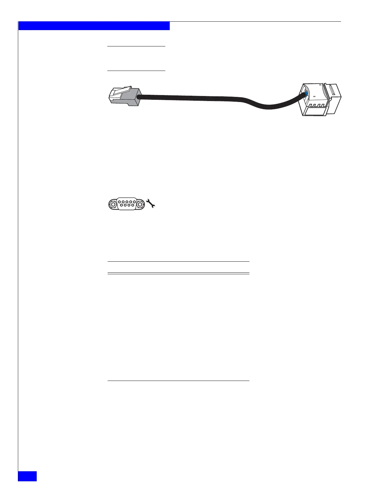
Figure 33 Example of Ethernet extension (modular plug to modular jack) cable
Control Station serial console (DB-9) plug connector
The back of the Block and File VNX5300 platform Control Station includes a standard
serial console Electronics Industries Association (EIA) RS-232 interface (DB-9) plug
connector (labeled with a symbol depicting a wrench on the right). Notice the
orientation of the pins (Figure 34).
Figure 34 Control Station serial console (DB-9) plug connector
Table 24 lists the Control Station Ethernet (DB-9) pin signals used on the connector.
Control Station modem (DB-9) plug connector
The back of the Block and File VNX5300 platform Control Station includes a standard
modem serial interface (DB-9) plug connector (labeled with a symbol depicting a
telephone handset on the left). Notice the orientation of the pins (Figure 35 on
page 37).
VNX-000564
CNS-001742
Pin 1
5
6
9
Table 24 Control Station (DB-9) plug connector pinout
DB-9 Pin Signal Description
1 CD Carrier detect
2 RXD Received data
3 TXD Transmitted data
4 DTR Data terminal ready
5 GND Ground
6 DSR Data set ready
7 RTS Request to send
8 CTS Clear to send
9 RI Ring indicator


 To Next Page