EMC® VNX5300™ Hardware Information Guide
38
EMC® VNX5300™ Hardware Information Guide
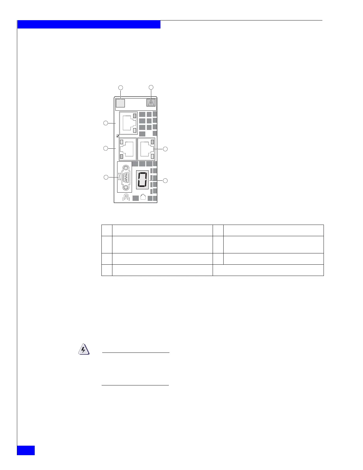
Data Mover management module
The Data Mover management module provides the management connections via
three 10/100/1000 Ethernet (RJ-45) ports. The Data Mover management module also
includes one RS-232 (EIA) DB-9 serial socket connector for service laptop connection
and several LEDs (Figure 37)
Figure 37 Data Mover management module
Data Mover management module Ethernet (RJ-45) NIC ports
The Block and File VNX5300 platform Data Mover management module comes with
three integrated dual-port Ethernet ports (labeled 0, 1, and 2) on the rear of the Data
Mover management module. These ports provide an interface for connecting to
10-Mb/s, 100-Mb/s, or 1000-Mb/s networks and provide full-duplex (FDX)
capability, which enables simultaneous transmission and reception of data.
To avoid electric shock, do not connect safety extra-low voltage (SELV) circuits to
telephone-network voltage (TNV) circuits. LAN ports contain SELV circuits, and
WAN ports contain TNV circuits. Some LAN and WAN ports both use RJ-45
connectors. Use caution when connecting cables.
To access the Ethernet ports, connect a Category 3, 4, 5, 5E, or 6 unshielded
twisted-pair (UTP) cable to the RJ-45 connector on the back of the Data Mover
management module, as described in Table 16 on page 28.
1 Power/fault LED 5 DB-9 serial console socket connector
2 Data Mover management module push button
latch handle
6 RJ-45 Ethernet NIC port (labeled 0)
3 RJ-45 Ethernet NIC port (labeled 1) 7 RJ-45 Ethernet NIC port (labeled 2)
4 DME ID numeric display


 To Next Page