System component description
39
EMC® VNX5300™ Hardware Information Guide
Since the Control Station and the Data Mover management module have the same
type of RJ-45 NIC ports, “Control Station Ethernet (RJ-45) NIC ports” on page 34
provides detailed information about the Data Mover management module NIC ports,
connector, and adapter.
Data Mover management module LEDs
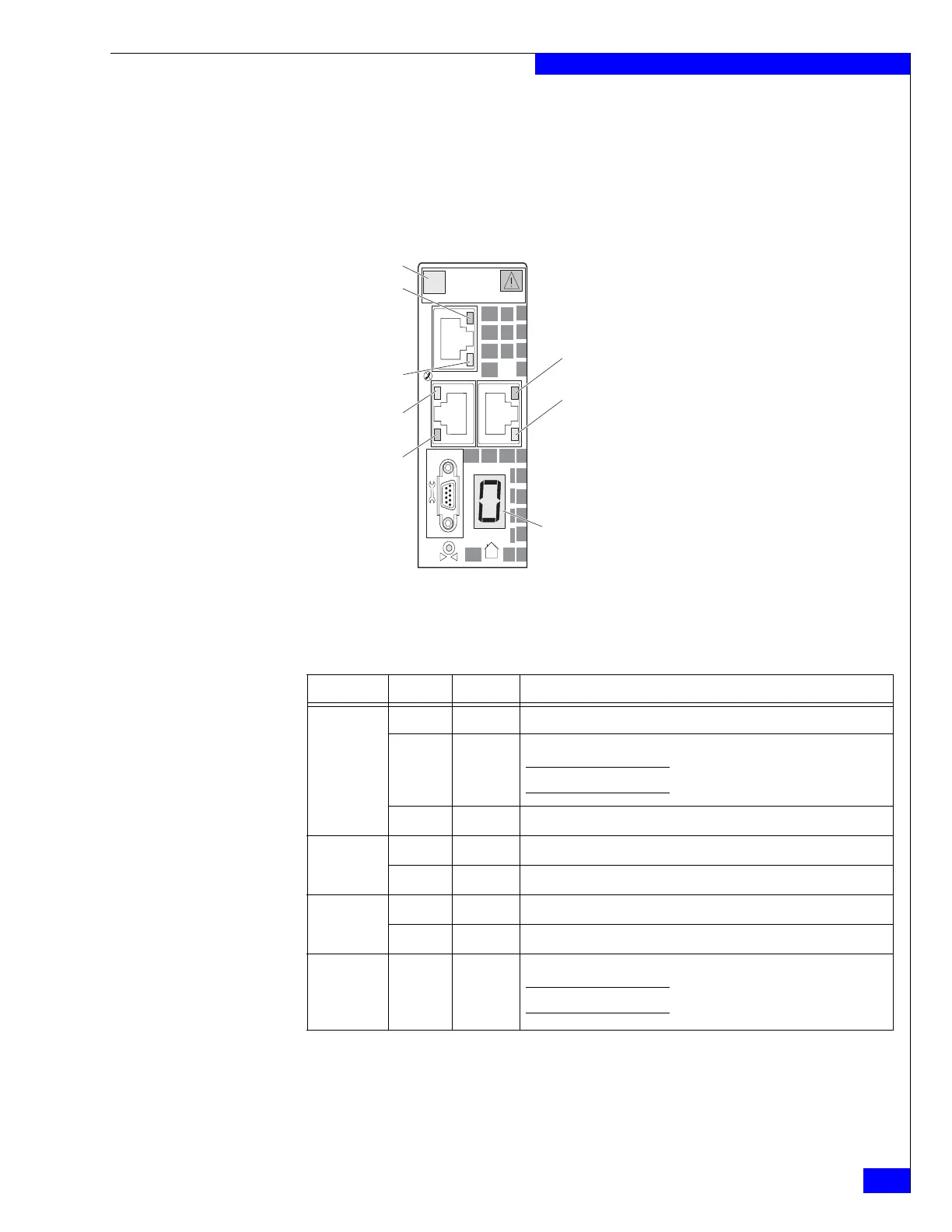
Figure 38 shows the LEDs and Table 26 describes them.
Figure 38 Data Mover management module LEDs
2
0
1
#
Port 2 (Link LED)
Port 0 (Link LED)
Numeric display
(DME ID)
Port 1 (Activity LED)
Power/Fault LED
Port 0 (Activity LED)
Port 2 (Activity LED)
Port 1 (Link LED)
CNS-001671
Table 26 Data Mover management module LEDs
LED Color State Description
Power/Fault Green On Data Mover management module is powered up.
Amber On Data Mover management module has faulted.
Note: LED is always illuminated at powerup, until it is initialized.
— Off Data Mover management module is powered down.
Link (each
port has one)
Green On Network connection
— Off No network connection
Activity (each
port has one)
Amber Blinking Transmit/receive activity
— Off No network activity
numeric
(7-segment)
display for
enclosure ID
— On Displays the enclosure ID assigned to the Data Mover Enclosure.
Note: Each enclosure is assigned a number at installation.


 To Next Page