17
Once verified previous steps proceed as follows:
- check that “BNC” of level probe has been connected as described in “Hydraulic
Installation” chapter.
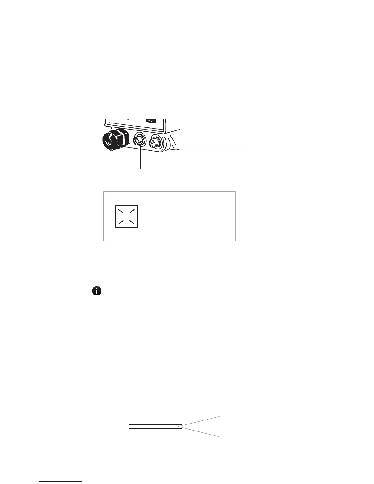
- connect “BNC” and external signal to pump’s “INPUT” connectors.
-braided shield cable; +center conductor
This input may be used as follows:
- as pulse sender water meter or
- as startup contact for “BATCH” mode or
- as voltage input for “VOLT” mode or
- as current input for “mA” mode
- connect alarm and/or stand-by signal as described below fig (E):
- proceed to “SEFL” connection (Flow sensor is optional) as described in page 56.
fig (E)
1
4
1: (Green) “Stand-by” Input
4: (Yellow) “Stand-by” Ground
2: (Brown) Alarm (Relay) Common
3: (White) N.O. Alarm(Relay) Contact
Max load relay output: free contact 1A 24VAC
2
3
Notes: - “Alarm” signal isn’t fuse protected
- “Standby” signal has main priority on pump’s enabling / disabling.
External Signal Input
Level Probe Input
IF NOT USED, PROTECT THE MINI DIN PLUG WITH THE BLACK RUBBER CAP LOOSE
IN THE ACCESSORIES BAG.
white - signal
yellow - ground
brown - + 12V
Connection to
water meter with
HALL effect
(option)
Metering pumps for connection to an Hall effect water meter have got a three wires signal cable.
If the water meter is equipped with the pump, there is a MPM plug to connect the pump.
Refer to ⎘ Main board connection.
Wires cable connections