48
Appendix I - Fluorine probe module & calibration
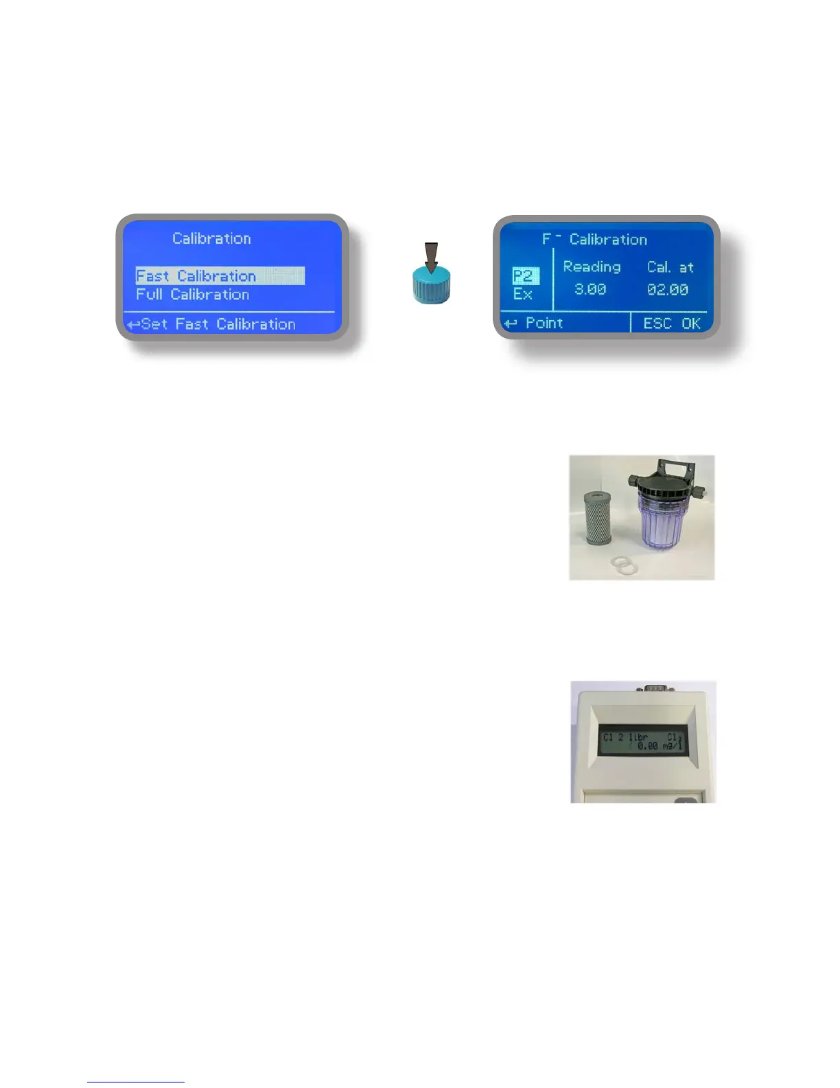
Carbon Filter System
Photometer
In the upper part of the motherboard there are two connectors for the installation of the probe modules. On request,
these modules are installed by the manufacturer. For the form of fluoride probe simply connect the probe’s BNC
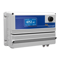
connector. The probe must be calibrated for properly operate. Chosoe FULL calibration for two points calibration
involing zero point (P1) and the second point (P2).
The FAST Calibration is performed by a single point from the value closest to work
Warning: This procedure assumes that instrument is correctly configured, it is connected to the probe running and
installed on your system. The measurement must be performed using the system water.
Otherwise, the results may not be reliable.
Zero point calibration (P1).
In the probe’s calibration menu move the cursor to “P1” and select it to enter
in the calibration procedure. For a correct calibration, proceed as follows:
- Install an “activated carbon filter” in the filter holder.
- Flow water inside the filter-holder for about 30 minutes.
- Press the knob with the cursor positioned on “Cal.at”. Remove the filter.
2nd calibration point (P2).
Move the cursor on “P2” and select to enter the calibration procedure.
For a correct calibration using a photometer or a DPD system to read the mg / l (F)
in the plant. Enter the value read in the “Cal. at “.
To complete the procedure, move the cursor to “OK” and press the wheel for saving.
If during calibration an error occurs, the instrument will signal with a message and
ask for a new calibration. Clear current settings or restore the default values.