4
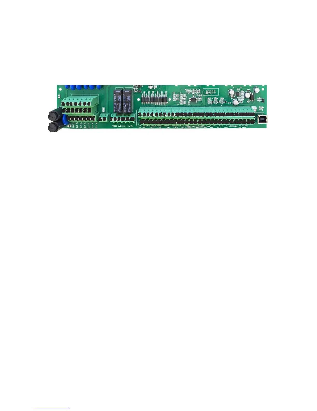
Mainboard Connections.
Unplug instrument from main power supply then perform connections to probes and / or selected outputs by following the
above picture. For easy understanding board as been divided into two parts: Power connections and I/O connections.
For EClx series probes, NTU connections and ETHERNET version, see APPENDIX A at page 30.
Power Connections:
F1: Main fuse (6.3AT)
F2: Circuit fuse (3.15AT)
LA - LB: Relay Output Disable Jumper (remove wire to disable outputs)
Main power supply (from 90VAC to 265VAC): L (live), E (earth), N(neutral)
Setpoint Outputs (VAC same on main power supply):
(free contact versione are NOT fuse protected with a max insulation of 250V)
1 - E - N (F2 fuse protected)
2 - E - N (F2 fuse protected)
3 - E - N (F2 fuse protected)
4 - E - N (F2 fuse protected)
5 - E - N (F2 fuse protected)
6 - E - N (F2 fuse protected)
Probe Cleaning output: 7(N.C.), 8(C), 9(N.O.) Voltage free contact
General Alarm output: 10(N.C.), 11(C), 12(N.O.) Voltage free contact
Warning: Connections must be perfomed by qualied and trained personnel only.
Block numbers are related only to its own part of the board.
]
Power Connections
]
I/O Connections
L 1 2 3 4 5 6
E E E E E E E
7 8 9 10 11 12
F1
F2
A B
29 30 31 32 33 34 35 36 37 38 39 40 41 42 43 44 45 46 47 48 49 50 51 52 53 54 55 56
1 2 3 4 5 6 7 8 9 10 11 12 13 14 15 16 17 18 19 20 21 22 23 24 25 26 27 28
N N N N N N N