*0°C / 4mA - 100°C / 20mA
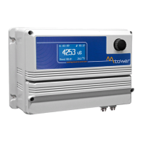
RS485:
26: + Signal RS485 (A)
27: - Signal RS485 (B)
Tank Level inputs:
29 (-) ; 30 (+) Level 1
31 (-) ; 32 (+) Level 2
33 (-) ; 34 (+) Level 3
35 (-) ; 36 (+) Level 4
37 (-) ; 38 (+) Level 5
Proximity Sensor (mod. “SEPR”) input:
39(+ Brown) ; 40(Black) ; 41(- Blue)
set ow option from setup menu
(Hall effect) pulse sender water meter: 42(+12VDC) ; 43(INPUT) ; 44(GND)
(Contact) Pulse sender water meter: 43(INPUT) ; 44(GND)
Temperature Probe input for mod. “PT100”** only: 50(green) ; 51(brown) ; 52(white) ; 53(yellow)
(remove resistance before to install probe)
Temperature Probe input for “PT100” with 50(green) ; 51(orange or pink) ; 52(white) ; 53(yellow)
ECDIND probe: (Ref. A Appendix - Inductive Conductivity module)
Standby signal input: 54(+) ; 55(GND)
*This is “FLOW1” for “MAX5 PH CL PH CL double ow” model only
**This is “TEMP2” for “MAX5 PH CL PH CL double ow” model only
OPTO COUPLED
SIGNALS
(-) is NOT a shared
signal !
OPTIONAL OUTPUTS
on demand
GND is a shared ground
(-) is a shared (GND)
ground signal !
OPTIONS
OPTIONS
OPTIONS