EasyManua.ls Logo

Emerson 1F95-1277 User Manual

Emerson 1F95-1277
14 pages
To Next Page IconTo Next Page
Page #1 background imageLoading...
Page #1 background image
Model Programming Choices
1F95-1277
7 Day 5+1+1 Day Non-Programmable
white-rodgers.com
emersonclimate.com
Blue Universal Touchscreen Thermostat with
Automatic Heat/Cool Changeover Option
PART NO. 37- 6753E
Replaces 37-6753D
1517
Single Stage, Multi-Stage, Heat Pump
Installation and Operating Instructions
APPLICATIONS
SPECIFICATIONS
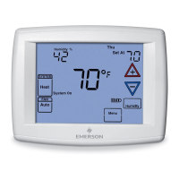
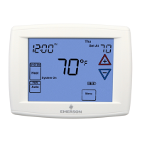
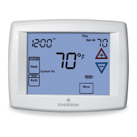
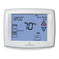
1F95-1277 Touchscreen Thermostat
Save these instructions for future use!
FAILURE TO READ AND FOLLOW ALL INSTRUCTIONS
CAREFULLY BEFORE INSTALLING OR OPERATING THIS
CONTROL COULD CAUSE PERSONAL INJURY AND/OR
PROPERTY DAMAGE.
THERMOSTAT APPLICATION GUIDE
Thermostat
Configuration Options
Thermostat
Applications
Maximum
Stages
Heat/Cool
Single Stage 1
No Heat Pump (SS1)
Gas, Oil, Electric, Heat Only,
Cool Only or Heat/Cool
Systems, 2 or 3 wire Hydronic
Zone (Hot Water or Steam)
Systems, 24 Volt or Millivolt
1+1
Multi Stage 2
No Heat Pump (MS2)
2+2
Heat Pump 1
Single Stage Compressor
Heat Pump (HP1)
Single Stage Compressor
Heat Pump Systems - up to 2
Stages Aux./Emergency Heat
3+1
Heat Pump 2
Two Stage or Two
Compressor Heat Pump
(HP2)
Two Stage or Two Compressor
Heat Pump systems - up to 2
Stages Aux./Emergency Heat
4+2
ATTENTION: MERCURY NOTICE
This product does not contain mercury. However, this
product may replace a product that contains mercury.
Mercury and products containing mercury must not be
discarded in household trash. Do not touch any spilled
mercury. Wearing non-absorbent gloves, clean up any
spilled mercury and place in a sealed container. For proper
disposal of a product containing mercury or a sealed
container of spilled mercury, place it in a suitable shipping
container. Refer to www.thermostat-recycle.org for
location to send the product containing mercury.
Index Page
Installation 2
Wiring Diagrams 3
Thermostat Quick Reference 4
Installer Configuration Menu 5
Operating Your Thermostat 9
Programming 10
Troubleshooting 13
Electrical Rating:
Battery Power .......................... mV to 30 VAC, NEC Class II, 50/60 Hz or DC
Input-Hardwire ......................... 20 to 30 VAC
Terminal Load ............................. 1.5A per terminal, 2.5A maximum all terminals combined
Setpoint Range ............................ 45 to 99°F (7 to 37°C)
Rated Differentials: Fast. Slow
Heat (Single Stage/Multi-Stage) ............ 0.6°F 1.5°F
Cool (Single Stage/Multi-Stage) ............ 1.2°F 1.7°F
Heat Pump ............................ 1.2°F 1.7°F
Emer Heat ............................ 0.6°F 1.7°F
Operating Ambient.......................... 32°F to +105°F (0 to +41°C)
Operating Humidity ......................... 90% non-condensing max.
Shipping Temperature Range ................. -40 to +150°F (-40 to +65°C)
Dimensions Thermostat...................... 4-9/16"H x 5-13/16"W x 1-3/16"D
To prevent electrical shock and/or equipment damage,
disconnect electric power to system at main fuse or
circuit breaker box until installation is complete.
CAUTION
!

Questions and Answers:

Emerson 1F95-1277 Specifications

General IconGeneral
TypeProgrammable Thermostat
DisplayBacklit LCD
Wi-Fi ConnectivityNo
Voltage24 VAC
ColorWhite
Power SourceBattery or C-Wire
Programmability7-day programmable
Featuresfilter change reminder

Summary

SPECIFICATIONS

Electrical Rating

Electrical characteristics and limits for system operation.

Setpoint Range

Defines the adjustable temperature limits for heating and cooling.

Rated Differentials

Specifies temperature differences for system cycling in various modes.

Operating Ambient

Outlines temperature and humidity limits for thermostat operation.

INSTALLATION

Remove Old Thermostat

Procedures for safely disconnecting and removing the existing thermostat.

Installing New Thermostat

Step-by-step guide for physically mounting the new thermostat base and unit.

Battery Location

Identifies the location and recommended type for backup batteries.

Power Stealing Switches

Explains the function of switches that draw power from the HVAC system.

WIRING DIAGRAMS

Single Stage and Multi-Stage Connections

Wiring schematics for standard HVAC systems without heat pumps.

Heat Pump Connections

Wiring diagrams specifically for various heat pump system configurations.

THERMOSTAT QUICK REFERENCE

Home Screen Description

Overview of the main display elements and their meanings.

Programming and Configuration Items

Summary of key features and settings available for user configuration.

INSTALLER/CONFIGURATION MENU

Configuration Menu Options

Comprehensive list of advanced settings for system setup and customization.

Select Reversing Valve

Configuration for the heat pump's reversing valve operation mode.

Programs per week

Selection of the scheduling format: 7-day, 5+1+1-day, or non-programmable.

System Switch Configuration

Definition of the thermostat's system modes (Heat, Cool, Auto, etc.).

OPERATING YOUR THERMOSTAT

Check Thermostat Operation

Basic steps to verify the thermostat is functioning correctly.

Fan Operation

How to control and test the HVAC system's fan.

Heating

Instructions for operating and testing the heating system.

Cooling

Instructions for operating and testing the cooling system.

Choose the System Setting

Guidance on selecting the appropriate operating mode (Heat, Cool, Auto, Off).

PROGRAMMING

Manual Operation (Bypassing the Program)

How to manually set a temperature that overrides the schedule.

Set Current Time and Day

Procedure for setting the thermostat's internal clock and calendar.

Automatic Daylight Saving Calculation

Feature for automatically adjusting the clock for DST.

Programming Tip: Copy Program

Method for efficiently copying program settings to other days.

Enter the Cooling Program

Steps to define cooling schedules and temperature setpoints.

Automatic Schedule

Utilizing the feature for simplified, automated temperature scheduling.

Energy Saving Factory Pre-Program

Overview of the default energy-saving programmed schedule.

Wired Remote Temperature Sensing

Setup and use of external sensors for room temperature monitoring.

TROUBLESHOOTING

Comfort Alert Codes

Interpretation of diagnostic codes indicating HVAC system faults.

Reset Operation

Procedure to reset the thermostat to factory defaults or resolve issues.

Symptom: No Heat/No Cool/No Fan (common problems)

Common issues and their likely causes and solutions.

Symptom: Furnace (Air Conditioner) Cycles Too Fast or Too Slow

Troubleshooting for HVAC system cycling frequency problems.

Related product manuals