July 2020
Installation, Operation and Maintenance Manual
VA-DC-000-1803 Rev. 2
22
Section 3: Actuator Reassembly
Actuator Reassembly
3.3.3 Refer to assembly drawing page 2 of 2 Detail "C". Install one rod wiper (4 - 10) into
inner end cap (3 - 10).
3.3.4 Install one rod bushing (4 - 20) into inner end cap (3 - 10).
3.3.5 Coat one Polypak seal (4 - 30) with lubricant and install, lip rst, into inner end
cap (3 - 10).
!
CAUTION
Polypak seal facing piston side. Install the Polypak seal with energizer ring facing outboard
side (away from housing).
3.3.6 Install one o-ring seal (4 - 90) into seal groove located on the inboard face of
inner end cap (3 - 10).
3.3.7 Install inner end cap (3 - 10) on to housing (1 - 10).
NOTE:
The pressure inlet port should be positioned in the same position as recorded in
Section 2.2, step 2.2.1.
3.3.8 Place lock washers (3 - 110) onto hex cap screws (3 - 100).
3.3.9 Install hex cap screws (3 - 100), with lock washers, through housing (1 - 10) and
into inner end cap (3 - 10).
3.3.10 Refer to assembly drawing page 2 of 2 Detail "D". Install one O-ring seal (4 - 70)
into the seal groove in piston rod (3 - 40).
3.3.11 Apply lubricant to two sets of rod T-seal components (4 - 50).
NOTE:
The T-seal is composed of one rubber seal and two split skive-cut back-up rings.
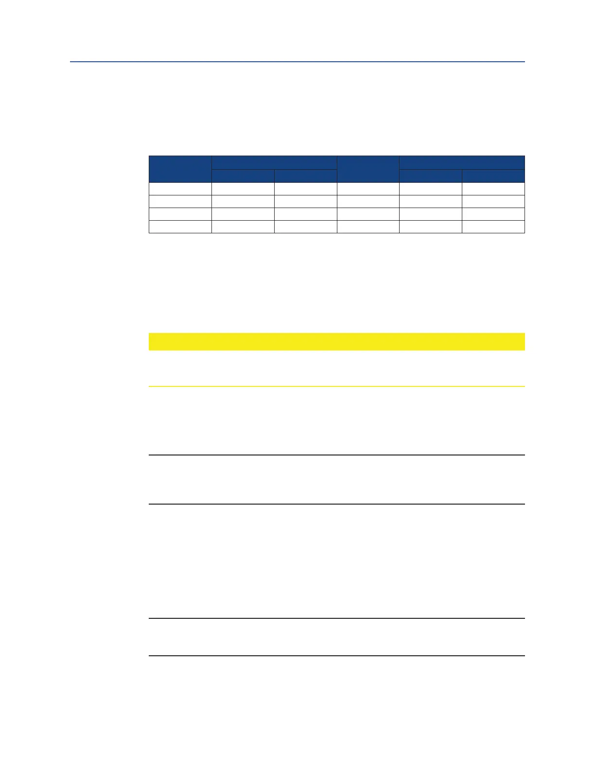
3.3.2 Torque tighten piston rod (3 - 40) to the lubricated torque as listed in the
following Table.
Table 3. Piston Rod Torque Information
Housing
Model
Torque (±5%)
Housing
Model
Torque (±5%)
lb-ft Nm lb-ft Nm
G01 50 122 G5 240 325
G2 90 122 G7 240 325
G3 90 122 G8 240 325
G4 240 325 G10 240 325
 Loading...


