Home
Emerson
Controller
Bettis G2 Series
Emerson Bettis G2 Series User Manual
5
of 1
of 1 rating
64 pages
Give review
Manual
Specs
To Next Page
To Next Page
To Previous Page
To Previous Page
Loading...
July 2020
Installation, Operation and Maintenance Manual
V
A-DC
-000-1803 R
ev. 2
50
Appendix
Appendix
Appe
ndix A:
List of Dra
wings
A
.1
Par
t No. 115680, GXXXX
-H Pneumatic
Assembly Drawing, Sheet 1 of 2
î
!
CAUTION
Latest dra
wings can be required from Eme
r
son.
Figure A-1
53
55
Table of Contents
Default Chapter
3
Table of Contents
3
Section 1: Introduction
5
General Service Information
5
Definitions
6
General Safety Information
6
Bettis Reference Materials
7
Service Support Items
7
Lubrication and Fluid Requirements
8
General Tool Information
8
Actuator Storage
8
Actuator Installation
9
Actuator Start-Up
9
Actuator Operation
10
Section 2: Actuator Disassembly
11
General Disassembly
11
Pneumatic Power Module Disassembly
11
Drive Module Disassembly
14
M18 Hydraulic Override Cylinder Disassembly
16
M18 Pump Disassembly
17
M18 Reservoir Disassembly
19
Section 3: Actuator Reassembly
20
General Reassembly
20
Drive Module Reassembly
20
Pneumatic Power Module Reassembly
25
G2 and G3 Early Model Pneumatic Power Module Reassembly
28
M18 Hydraulic Override Cylinder Reassembly
31
M18 Pump Reassembly
33
M18 Reservoir Reassembly
35
Actuator Testing
36
Section 4: Field Conversions
37
Construction Reversal (Exchange Module Locations)
37
Section 5: Module Removal and Installation
38
Pneumatic Power Module Removal
38
Pneumatic Power Module Installation
38
M18 Hydraulic Overrides Cylinder Removal
39
M18 Hydraulic Override Cylinder Installation
40
Power Swivel Module Removal
41
Power Swivel Module Installation
42
Section 6: Actuator Support Information
43
Module Weights by Item Number and Actuator Housing Size
43
G01 Tool Style and Wrench Size
45
G2 Tool Style and Wrench Size
45
G3 Tool Style and Wrench Size
46
G4 Tool Style and Wrench Size
46
G5 Tool Style and Wrench Size
47
G7 Tool Style and Wrench Size
47
G8 Tool Style and Wrench Size
48
G10 Tool Style and Wrench Size
48
M18 Tool Style and Wrench Size
49
Section 7: Troubleshooting
50
Fault Insertion
50
Operational Test
51
Section 8: Removal and Decommissioning
52
Removal and Decommissioning
52
List of Tables
53
Appendix A: List of Drawings
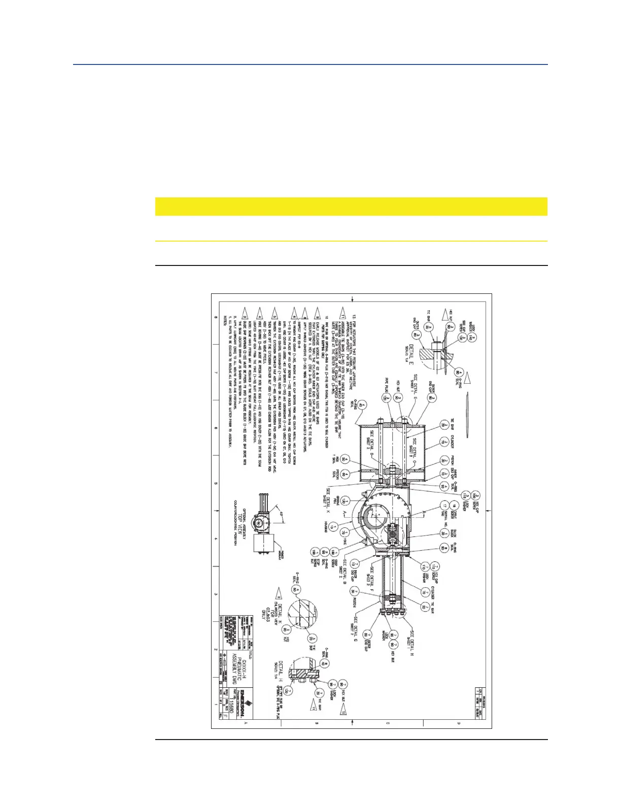
54
Part No. 115680, GXXXX-H Pneumatic Assembly Drawing, Sheet 1 of 2
54
Part No. 115680, GXXXX-H Pneumatic Assembly Drawing, Sheet 2 of 2
55
Part No. VA-ED-005-1120, M18 Assembly Drawing, Sheet 1 of 7
56
Part No. VA-ED-005-1120, M18 Assembly Drawing, Sheet 2 of 7
57
Part No. VA-ED-005-1120, M18 Assembly Drawing, Sheet 3 of 7
58
Part No. VA-ED-005-1120, M18 Assembly Drawing, Sheet 4 of 7
59
Part No. VA-ED-005-1120, M18 Assembly Drawing, Remote Mounting Installation, Sheet 5 of 7
60
Part No. VA-ED-005-1120, M18 Assembly Drawing, Auto Reset Installation, Sheet 6 of 7
61
Part No. VA-ED-005-1120, M18 Assembly Drawing, Hydraulic Schematic, Sheet 7 of 7
62
Other manuals for Emerson Bettis G2 Series
Disassembly And Reassembly
58 pages
5
Based on 1 rating
Ask a question
Give review
Questions and Answers:
Need help?
Do you have a question about the Emerson Bettis G2 Series and is the answer not in the manual?
Ask a question
Emerson Bettis G2 Series Specifications
General
Brand
Emerson
Model
Bettis G2 Series
Category
Controller
Language
English
Related product manuals
Emerson Bettis G Series
68 pages
Emerson Bettis G4 Series
64 pages
Emerson Bettis G7 Series
64 pages
Emerson Bettis G01 Series
64 pages
Emerson Bettis G4 SR Series
68 pages
Emerson Bettis 500
102 pages
Emerson Bettis XTE3000
175 pages
Emerson Bettis M Series
30 pages
Emerson Bettis CBB Series
33 pages
Emerson Bettis CBA1030-SR
31 pages
Emerson BETTIS E796 2000 M2CP
23 pages
Emerson Bettis CBA830-SR-M3HW
31 pages