7
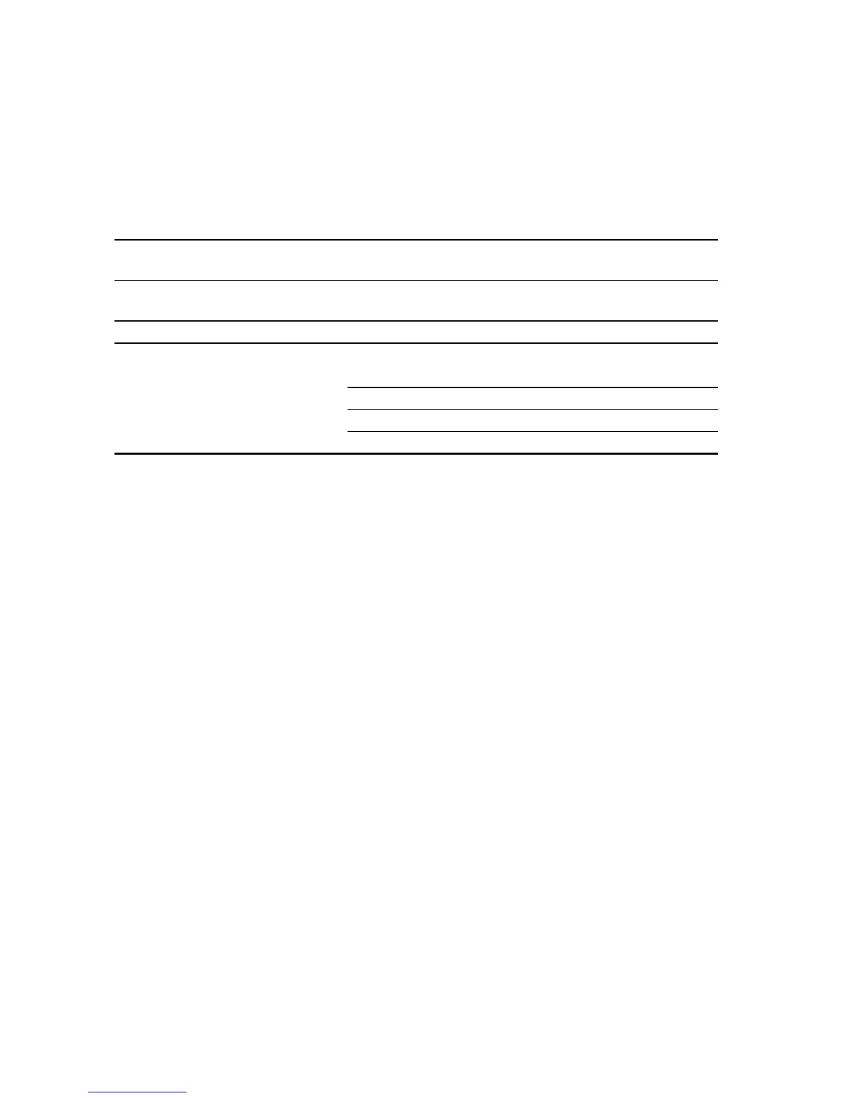
Maximum wiring distances
Use these guidelines for calculating maximum wiring distances.
Maximum distance between sensor and transmitter depends on cable
type. See Table 1.
.
The sensor is shipped with 10 feet (3 meters) of cable for connecting to
the remote booster amplifier. For longer cable lengths, up to 60 ft (20 m),
contact Micro Motion.
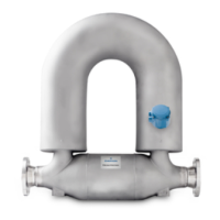
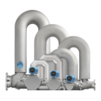
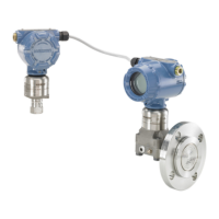
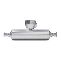
STEP 2. Orienting the sensor
The sensor will function properly in any orientation if the sensor tubes
remain filled with process fluid. Micro Motion recommends orienting the
CMF400 sensor as shown in Figure 5.
Flow direction arrow
The sensor has a flow direction arrow (see Figures 1-4) to help you
configure the transmitter for flow direction. If possible, install the sensor
so that the flow direction arrow matches actual process flow.
Table 1. Maximum cable lengths
Cable type Wire gauge Maximum length
Micro Motion 9-wire to an MVD
transmitter or core processor
Not applicable 60 feet (20 meters)
Micro Motion 9-wire to all other
transmitters
Not applicable 1000 feet (300 meters)
Micro Motion 4-wire Not applicable 1000 feet (300 meters)
User-supplied 4-wire
• Power wires (VDC) 22 AWG
(
0,35 mm
2
) 300 feet (90 meters)
20 AWG (0,5 mm
2
) 500 feet (150 meters)
18 AWG (0,8 mm
2
) 1000 feet (300 meters)
• Signal wires (RS-485) 22 AWG (0,35 mm
2
) or larger 1000 feet (300 meters)