EasyManua.ls Logo

Emerson CMF400 User Manual

Emerson CMF400
24 pages
To Next Page IconTo Next Page
Page #1 background imageLoading...
Page #1 background image
Micro Motion
TM
Micro Motion
®
CMF400 Sensor
Installation Instructions
Quick Reference Guide
P/N 3006075, Rev. D
May 2003
For online technical support, use the EXPERT
2
™ system at
www.expert2.com. To speak to a customer service
representative, call the support center nearest you:
In the U.S.A., phone 1-800-522-MASS
(1-800-522-6277)
In Canada and Latin America, phone
(303) 530-8400
In Asia, phone (65) 6770-8155
In the U.K., phone 0800 - 966 180 (toll-free)
Outside the U.K., phone +31 (0) 318 495 670
Question and Answer IconNeed help?

Do you have a question about the Emerson CMF400 and is the answer not in the manual?

Emerson CMF400 Specifications

General IconGeneral
BrandEmerson
ModelCMF400
CategoryAccessories
LanguageEnglish

Summary

BEFORE YOU BEGIN

INTRODUCTION

Installation Options Overview

STEP 1. Determining Installation Location

General Installation Guidelines

Hazardous Area Considerations

Ensures proper installation in hazardous environments according to area classification and safety directives.

Environmental Operating Limits

Specifies temperature limits for process fluid and ambient conditions for sensor operation.

STEP 2. Sensor Orientation and Flow Direction

Maximum Wiring Distances

Guidelines for calculating maximum wiring distances between sensor and transmitter based on cable type.

Flow Direction Indicator

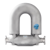
Identifies the flow direction arrow for correct transmitter configuration.

STEP 3. Mounting the Sensor

STEP 4. Booster Amplifier Wiring

Remote Booster Amplifier Wiring Details

Details on wiring the remotely mounted booster amplifier, including power requirements and connection figures.

STEP 5. Sensor to Transmitter Wiring

Wiring Installation Options

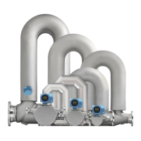
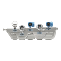
Describes the two sensor configurations: core processor with 4-wire cable or 9-wire junction box.

Core Processor 4-Wire Wiring

Instructions for connecting wiring at the core processor using shielded or armored cable.

9-Wire Junction Box Cable Wiring

STEP 6. Grounding the Sensor

Related product manuals