48
EN Drive Installation Manual
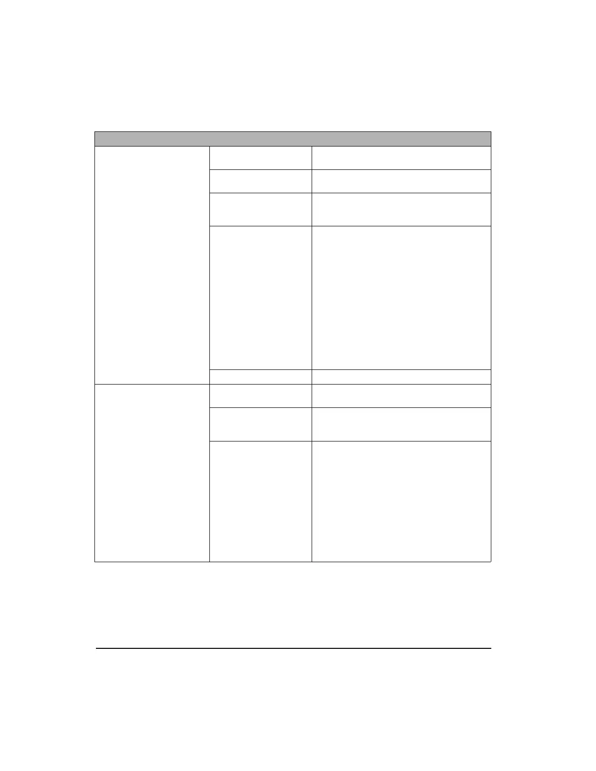
Control Inputs
Analog Command:
(1) ±10 VDC 14 bit, 100 kOhm impedance,
Differential
Analog Maximum Voltage
Input Rating:
Differential = +/- 14 VDC, each input with reference
to analog ground = +/- 14 VDC
Digital Inputs:
(5) 10-30 VDC, 2.8 kOhm impedance; current
sourcing signal compatible (active high); max input
response time is 500 µs; optically isolated
Pulse:
Interface: Software selectable differential (RS-422) or
single ended (TTL Schmitt Trigger)
Maximum Input Frequency:
Differential - 2 MHz per channel; 50% duty cycle (8
MHz count in quadrature)
Single ended - 1 MHz per channel; 50% duty cycle
(4 MHz count in quadrature)
Input Device = AM26C32
V
diff
= 0.1 - 0.2 V
V
common mode
max = +/- 7 V
Input impedance each input to 0 V = 12 - 17 kOhm
Motor Overtemperature:
(1) 0 to +5 VDC, 10 kOhm impedance, Single ended
Control Outputs
Analog Outputs (Diagnostic):
(2) ±10 VDC (single ended, 20 mA max) 10 bit
software selectable output signals
Digital Outputs:
(3) +10-30 VDC, 150 mA max, current sourcing,
(active high) optically isolated: Input debounce:
Programmable range, 0 to 200 ms
Pulse Differential:
Differential line driver, RS-422 and TTL compatible
20 mA per channel, sink and/or source
Scalable in one line increment resolution up to 2048
lines/rev of the motor (MG and NT)
Output Device = AM26C31
V
out Hi
@ 20 mA = 3.8 - 4.5 V
V
out Lo
@ 20 mA = 0.2 - 0.4 V
V
out diff
w/100 Ohm termination = 2.0 - 3.1 V
V
out common mode
w/100 Ohm termination = 0.0 - 3.0 V
I
out short circuit
= 30 - 130 mA
EN Drive Specifications
Artisan Technology Group - Quality Instrumentation ... Guaranteed | (888) 88-SOURCE | www.artisantg.com
 Loading...