C-14 / Appendix C - Hardware Installation Guide CI-ControlWave EFM
connected to Chassis Ground when they have been installed and secured via their two
Captured Panel Fasteners. As an extra added precaution, it is recommended that a #14
AWG wire be run from SCM Power Connector TB1-3 (Chassis Ground) to the same
known good Earth Ground. The following considerations are provided for the
installation of ControlWave EFM system grounds.
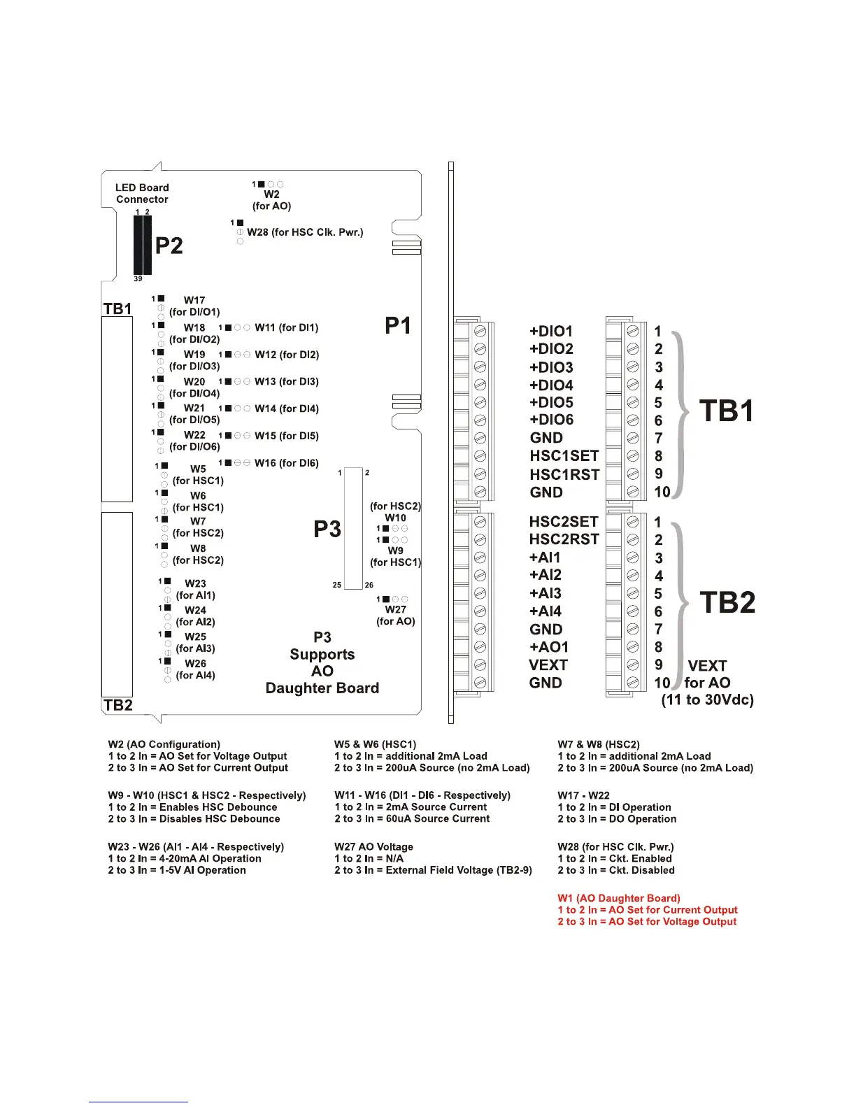
Figure C-9 - Non-isolated Mixed I/O Module Configuration Diagram