CI-ControlWave EFM Appendix C - Hardware Installation Guide / C-15
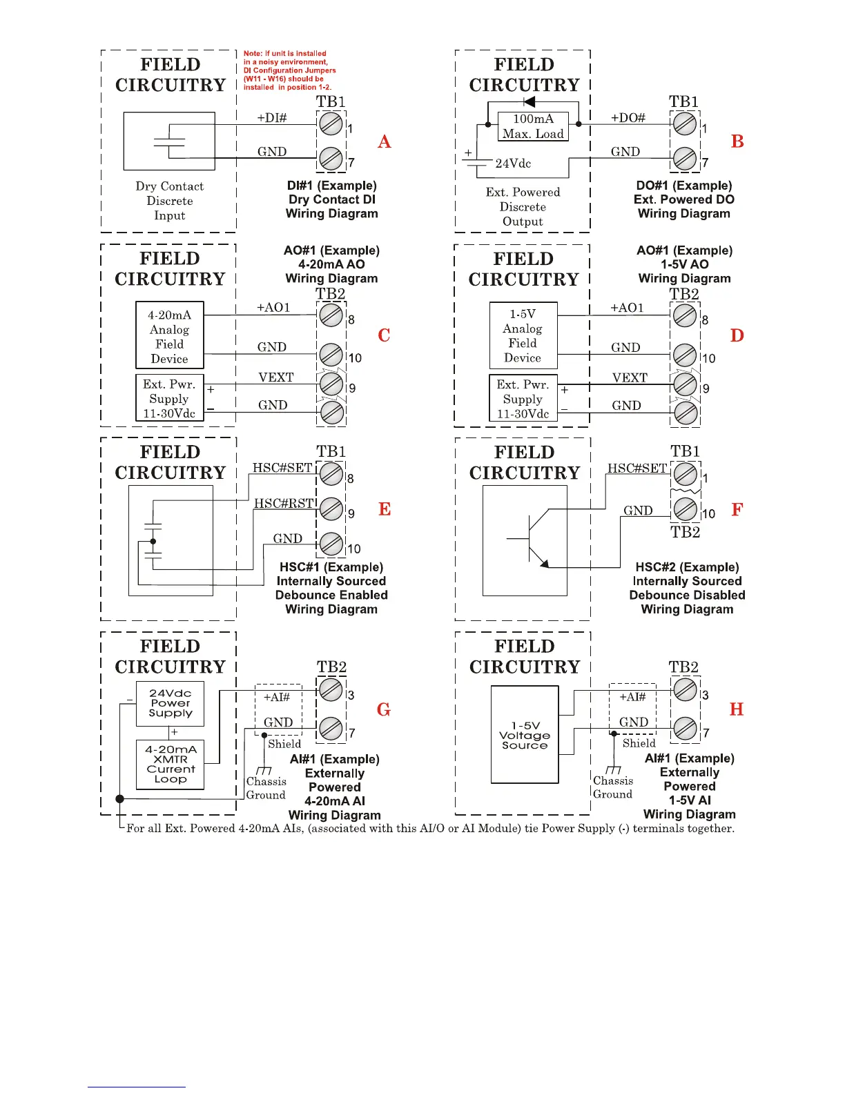
Figure C-10 - Non-isolated Mixed I/O Module Wiring Diagram
(see Figure C-9 for Mixed I/O Module Configuration Diagram)
• Chassis Ground Lug to Earth Ground wire size should be #4 AWG. It is
recommended that stranded copper wire is used and that the length should be as
short as possible.
• This ground wire should be clamped or brazed to the Ground Bed Conductor (that is
typically a stranded copper AWG 0000 cable installed vertically or horizontally).