CI-ControlWave EFM Appendix G - Radio Ready Installation Guide / G-5
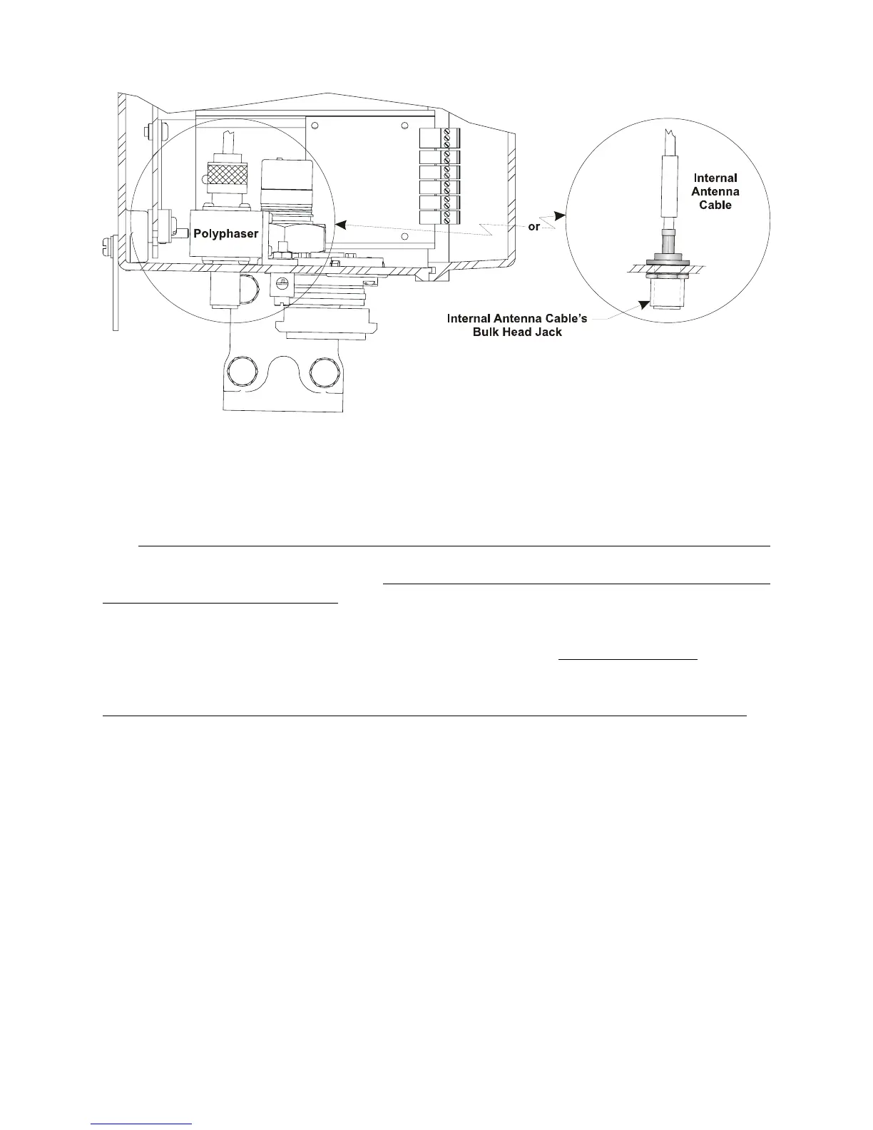
Figure 3 - Partial View - ControlWave EFM
with/without Polyphaser Installed
G2.2 ADDITIONAL FreeWave INFORMATION
The FreeWave Spread Spectrum Data Transceiver Model FGRM-501X005 User Manual
contains in-depth details on modem parameters, operation, installation, tuning transceiver
performance, and more. Copies of the FreeWave Spread Spectrum Data Transceiver Model
FGRM-501X005 User Manual can be obtained from FreeWave Technologies, Inc.
(electronically) by contacting their Technical Support Group.
FreeWave Tech. Support can be reached at 303-444-3862 or at www.freewave.com
.
Follow the “Tuning Transceiver Performance” section of the FreeWave Technologies, Inc.
FreeWave Spread Spectrum Data Transceiver Model FGRM-501X005 User Manual
to
configure the radio.
Note:
The setup program is invoked by connecting the radio to any PC
equipped with a terminal program (such as HyperTerminal), set-
ting the parameters for that terminal to those of Table 1, and
putting the radio into setup mode.
Connection to the PC requires a special RS-232 cable with a 9-pin
Female D-Type connector on the PC side and a 10-pin Female
MTA-100 Connector assembly on the radio side. A cable can be
constructed as illustrated in Figure 4. The terminal program must
be running before invoking the setup program. The setup
program is invoked by shorting MTA-100 Connector pins 4 (GND)
and 2 (MENU) together.