D7.8.4/0112-0415/E 12/17
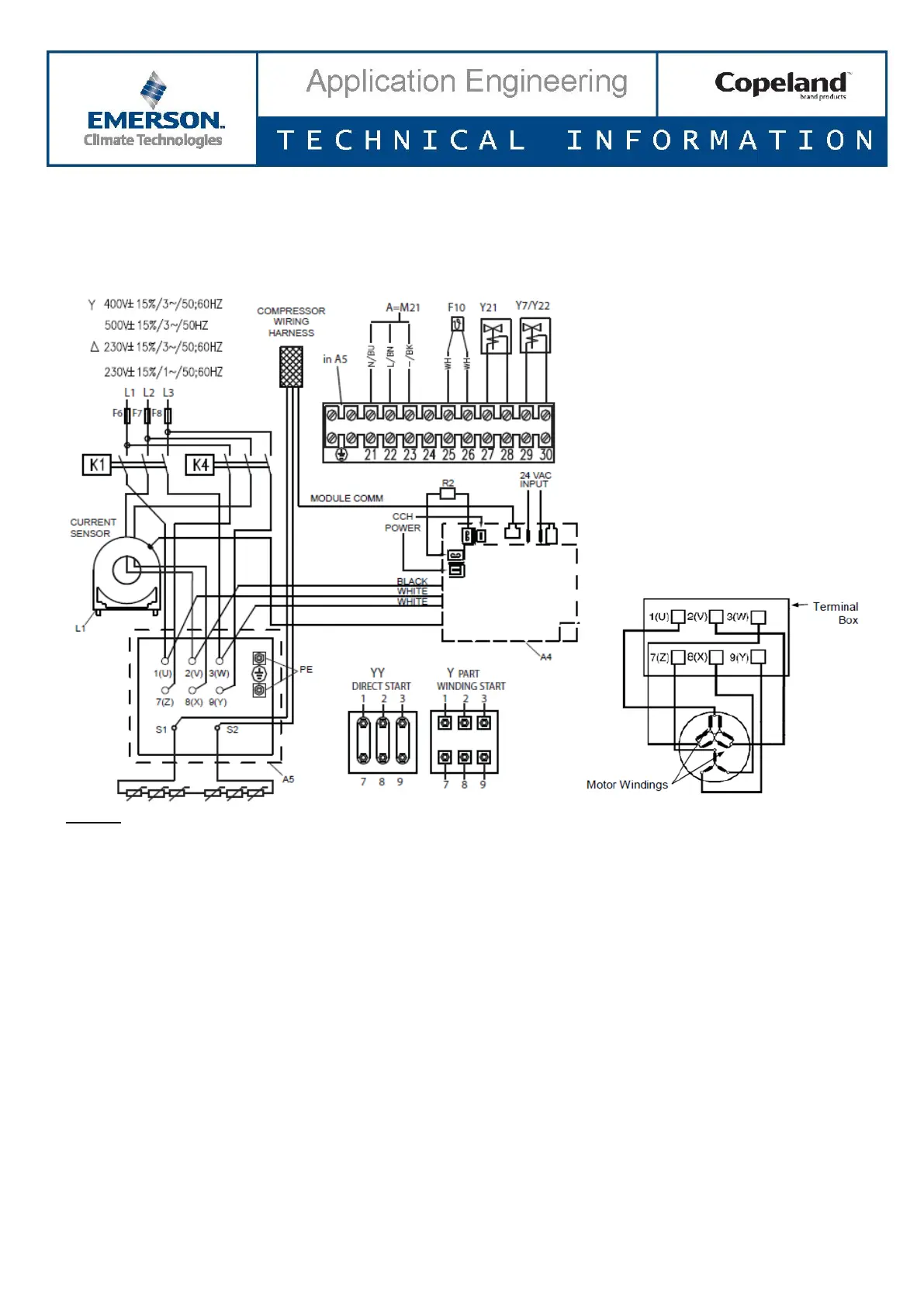
4.2.3 CoreSense Diagnostics with part winding
If using the CoreSense Diagnostics module with a part-winding start motor, one power lead of each of the windings
should be passed through the current sensing transformer in the same direction (see Figures 14 & 15) to provide
accurate compressor proofing. If the leads (L2 and L8 in picture below) are not routed in the same direction, the
running current may indicate close to zero.
Legend
A4 ........ Sensor module K1 ....... Contactor M1
A5 ........ Terminal box compressor K4 ....... Contactor M1 for second part winding
CCH .... Crankcase heater M21 ..... Fan motor/condenser
F6 ........ Fuse for control circuit R2 ....... Crankcase heater
F7 ........ Fuse for control circuit Y21 ..... Solenoid valve capacity control 1
F8 ........ Fuse for control circuit Y22 ..... Solenoid valve capacity control 2
F10 ...... Thermal protection switch M21
Figure 14: Wiring part winding
 Loading...


