Technical Guide
DAN-LIQ-TG-44-rev0813
November 2013
34
Section 6
DIGITAL AND TWO-STAGE ELECTRIC SHUT-OFF VALVES
Model 788 DVC Digital Control Electric Shut-off Valves
These valves are normally closed (N.C.) and they will open only when both solenoids are energized. The valves are fail-safe
as they close upon loss of power. They use the line product as the source of hydraulic power to open and close the main valve
piston. An electrical supply controlled by an electronic preset is the source of power for energizing the two solenoids.
These valves are used mainly for batching and they provide a means of reducing the rate of flow on startup and before final shut-
off of a predetermined delivery. This minimizes surges of pressure and line shock and assures + 1/4 gallon shut-off (sizes 2 inch
- 6 inch) of the preset volume.
The total system generally consists of three pieces of equipment: (1) a flowmeter, (2) electronic preset with digital control, and
(3) a digital electric control valve. The electronic preset is the device used to set the predetermined volume of liquid that is to be
delivered by the valve.
Operational Sequence
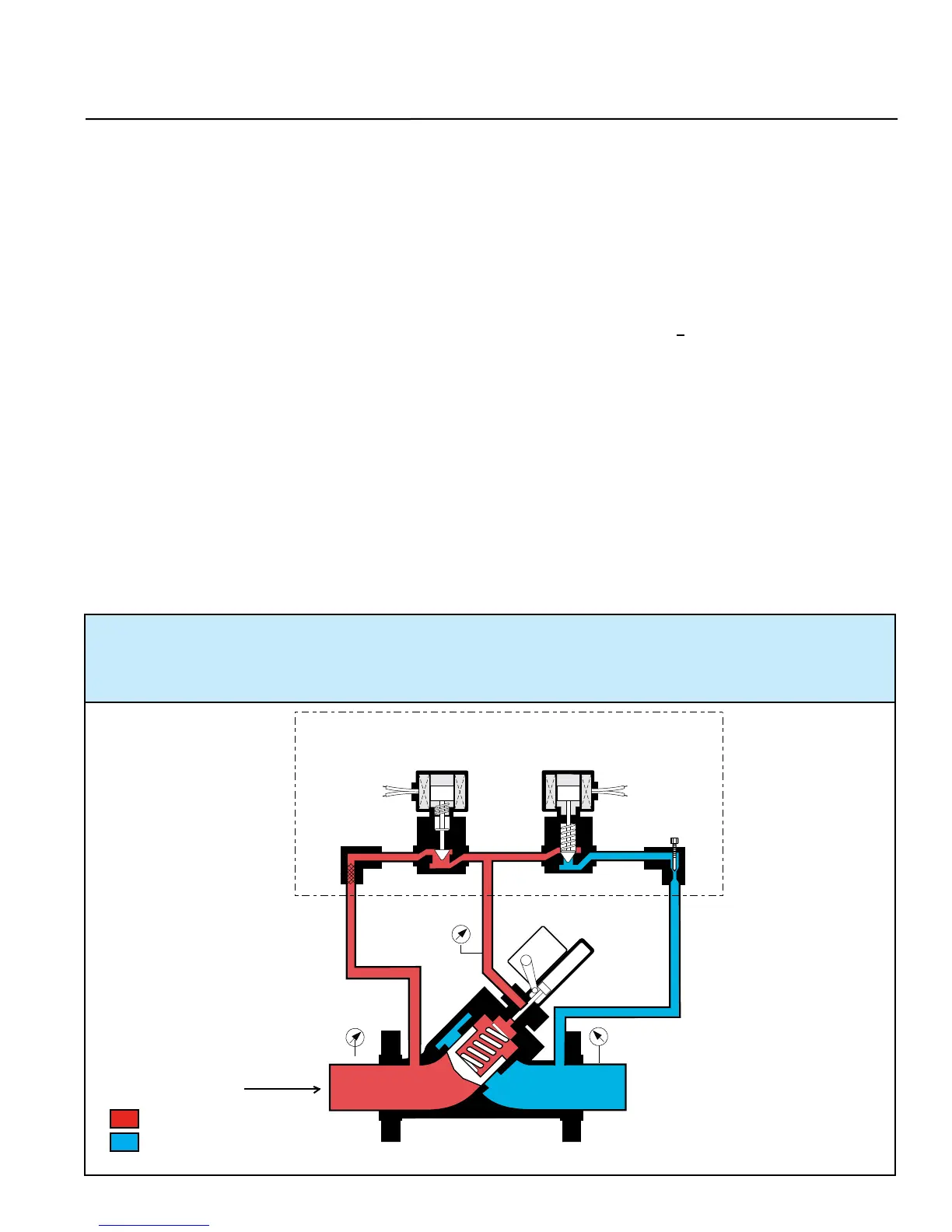
With both solenoids de-energized, the main valve is closed as shown in Figure 6-1. The main valve can be infinitely positioned
anywhere between 0 - 100% open by digital control of the solenoids. With both solenoids energized, as shown in Figure 6-3, the
valve begins to open. It will only open to the programmed flow rate set in the electronic preset. Normally, the electronic preset
is programmed to digitally control low flow start-up, maximum flow rate, low flow rate before shut-off and no flow. The electronic
preset will automatically energize and de-energize the solenoids to position the main valve to limit the required flow rate. When
the required flow rate is reached, the solenoids will be as shown in Figure 6-2. This hydraulically locks the main valve piston
in position. Should flow increase, the valve will close slightly to adjust to the required flow rate. All of the positioning is done by
digitally controlling the two solenoids as shown in Figure 6-1, 6-2 and 6-3.
CLOSED POSITION - The normally closed solenoid is closed. The normally open solenoid is open. Y-port (P3)
to Z-port (P2) is closed. X-port (P1 and Y-port (P3) pressures are balanced. The main valve spring being the
differential force, closes the piston and keeps it seated.
Figure 6-1
= Inlet Pressure
= Outlet Pressure
Limit
Switch
Position
Indicator
X
Z
Y
Y
X
Z
Y
X
Z
Y
P2
P1
P3
Flow
Solenoid Pilot (N.O.) Solenoid Pilot (N.C.)
Strainer
Needle
Valve
 Loading...