Technical Guide
DAN-LIQ-TG-44-rev0813
November 2013
43
TWO STAGE VALVES
Model 578 (N.C.) Two-stage Electric Shut-off Valve
Two-Stage Control electric shut-off valves are normally closed (N.C.) and they will open only when both solenoids are energized.
The valves are fail-safe as they close upon loss of auxiliary power medium. They use an auxiliary power source (typically
regulated instrument air) to open and position the valve for high and low flow. Flow limiting control is not available. An electrical
supply controlled by a preset is the source of power for energizing the two solenoids.
These valves are used mainly for batching and they provide a means of reducing the rate of flow on startup and before final
shut-off of a predetermined delivery. This minimizes surges of pressure and line shock and assures ±1/4 gallon shut-off (sizes
2" - 6") of the preset volume.
The total system consists of four pieces of equipment: (1) a flow meter, (2) a preset counter, (3) dual sequencing switches, and
(4) a two-stage electric shut-off valve. The preset counter is the device used to set the predetermined volume of liquid that is
to be controlled by the valve. The valve closes in two stages. The first stage closure reduces the flow rate through the valve to
approximately 10% to 20% of the rated capacity of the meter. The second stage closes the valve when the predetermined volume
of liquid has passed through the meter. See Figures 7-8, 7-9 and 7-10.
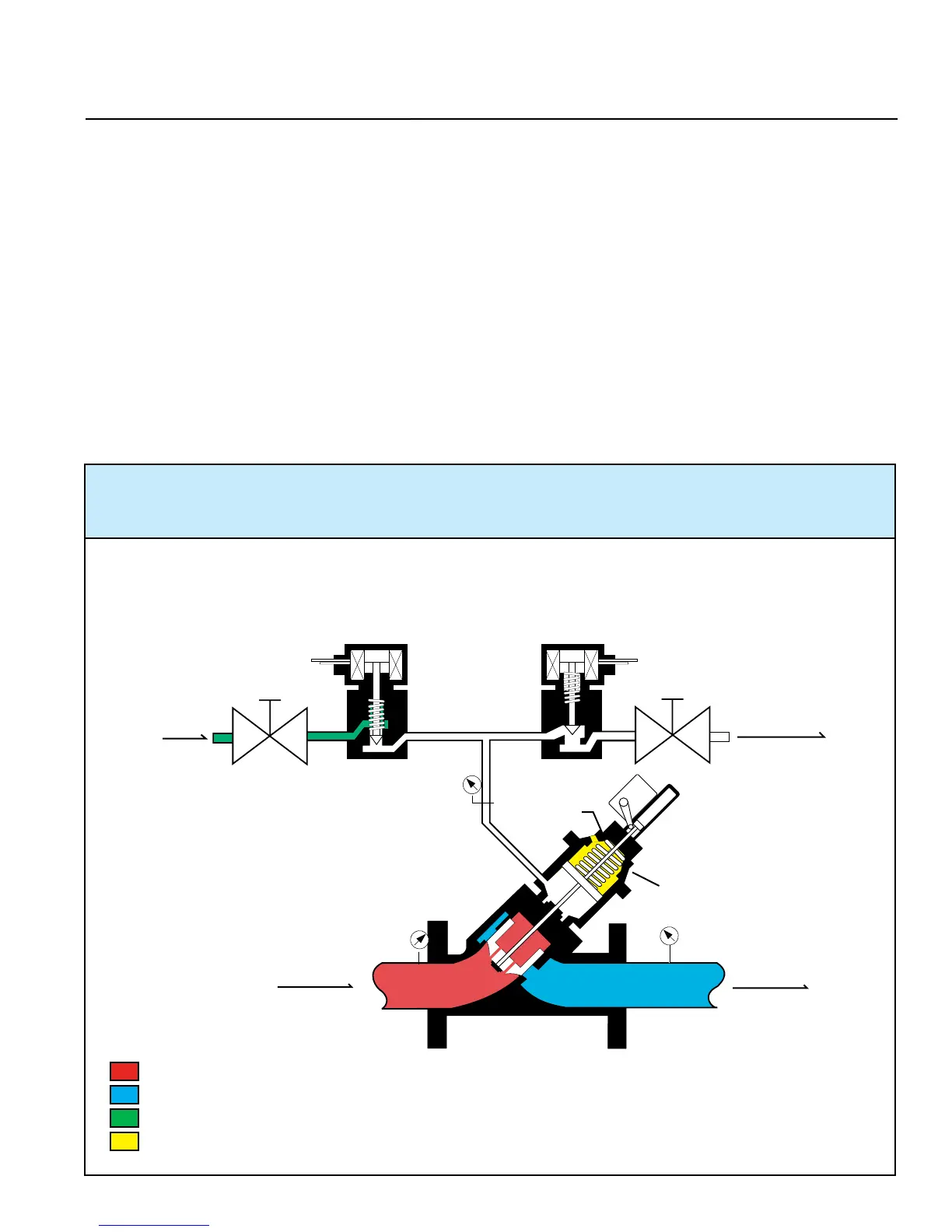
CLOSED POSITION - The normally closed solenoid is closed. The normally open solenoid is open, venting the
power cylinder pressure (P3) to atmosphere. The power cylinder spring provides the differential force to close
the main valve piston and keep it seated. The closing speed needle valve controls the closing speed.
40
Figure 7-8
= Inlet Pressure
= Outlet Pressure
= Power Cylinder Supply Pressure
= Power Cylinder Spring Force
Solenoid (N.O.)Solenoid (N.C.)
Opening
Speed
Closing
Speed
Supply
Pressure
(30 PSI Max)
Exhaust
Power
Cylinder
Vent
Flow
P2
P1
P3
 Loading...