Technical Guide
DAN-LIQ-TG-44-rev0813
November 2013
DIGITAL CONTROL VALVES
Model 588 DVC (N.C.) Digital Control Electric Shut-off Valve
Digital Control electric shut-off valves are normally closed (N.C.) and they will open only when both solenoids are energized. The
valves are fail-safe as they close upon loss of auxiliary power medium. They use an auxiliary power source (typically regulated
instrument air) to open and position the valve. An electrical supply controlled by an electronic preset is the source of power for
energizing the two solenoids.
These valves are used mainly for batching and they provide a means of reducing the rate of flow on startup and before final shut-
off of a predetermined delivery. This minimizes surges of pressure and line shock and assures ±1/4 gallon shut-off (sizes 2" - 6")
of the preset volume.
The total system generally consists of three pieces of equipment: (1) a flowmeter, (2) electronic preset with digital control, and
(3) a digital electric control valve. The electronic preset is the device used to set the predetermined volume off liquid that is to be
delivered by the valve.
Operational Sequence
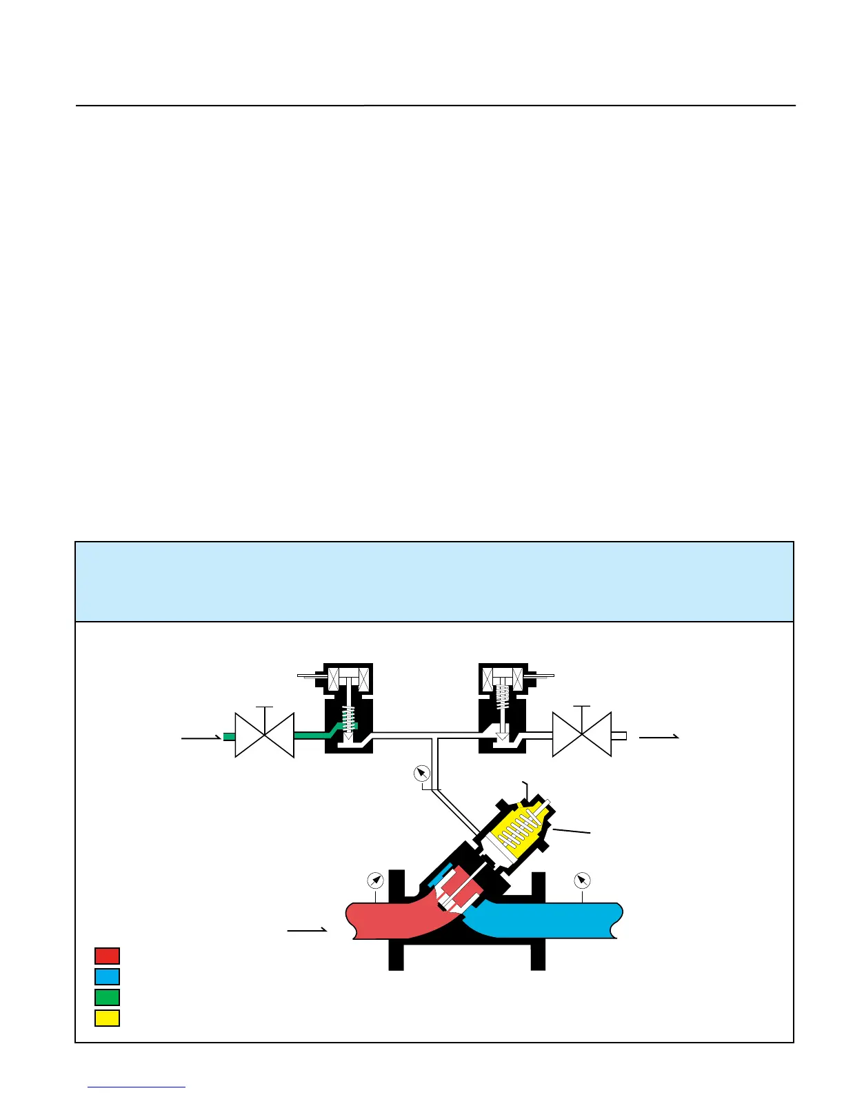
With both Solenoids de-energized, the main valve is closed as shown in Figure 7-5. The main valve can be infinitely positioned
anywhere between 0-100% open by digital control of the solenoids. With both solenoids energized, as shown in Figure 7-7, the
valve begins to open. It will only open to the programmed flow rate set in the electronic preset. Normally, the electronic preset
is programmed to digitally control low flow start-up, maximum flow rate, low flow rate before shut-off and no flow. The electronic
preset will automatically energize and de-energize the solenoids to position the main valve to limit the required flow rate. When
the required flow rate is reached, the solenoids will be as shown in Figure 7-6. This pneumatically locks the power cylinder piston
in position. Should flow increase, the valve will close slightly to adjust to the required flow rate. All of the positioning is done by
digitally controlling the two solenoids as show in Figure 7-5, 7-6 and 7-7.
CLOSED POSITION - The normally closed solenoid is closed. The normally open solenoid is open, venting the
power cylinder pressure (P3) to atmosphere. The power cylinder spring provides the differential force to close
the main valve piston and keep it seated. The closing speed needle valve controls how fast the valve closes
or responds to a flow rate change.
Figure 7-5
45
38
= Inlet Pressure
= Outlet Pressure
= Power Cylinder Supply Pressure
= Power Cylinder Spring Force
P2
P1
P3
Solenoid (N.O.)Solenoid (N.C.)
Opening
Speed
Closing
Speed
Supply
Pressure
(30 PSI Max)
Exhaust
Power
Cylinder
Vent
Flow
Figure 7-5
 Loading...