Quick Start
Commissioning
16 Digistart IS User Guide
www.controltechniques.com Issue: 4
Many electronic components are sensitive to static electricity. Voltages so low that they cannot be felt, seen or heard,
can reduce the life, affect performance, or completely destroy sensitive electronic components. When performing
service, proper ESD equipment should be used to prevent possible damage from occurring.
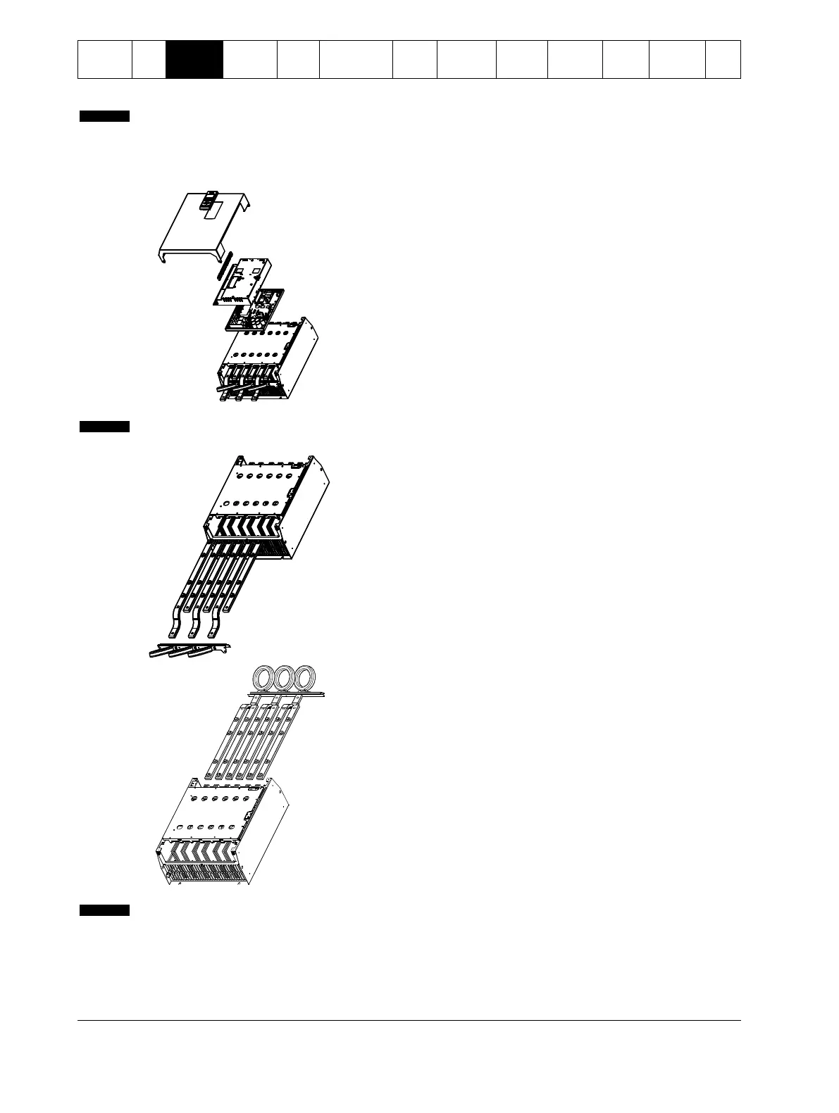
All units are manufactured with input and output busbars at the bottom of the unit as standard. The input and/or output busbars can
be moved to the top of the unit if required.
1. Remove all wiring and links from the soft starter before
dismantling the unit.
2. Remove the unit cover (4 screws).
3. Remove the keypad faceplate, then gently remove the
keypad (2 screws).
4. Remove the control terminal plugs.
5. Gently fold the main plastic away from the starter (12
screws).
6. Unplug the keypad loom from CON 1 (see note).
7. Label each SCR firing loom with the number of the
corresponding terminal on the backplane PCB, then unplug
the looms.
8. Unplug the thermistor, fan and current transformer wires
from the model board.
9. Remove the plastic tray from the starter (four screws).
Remove the main plastic slowly to avoid damaging the keypad wiring loom which runs between the main plastic and the
backplane PCB.
10. Unscrew and remove the magnetic bypass plates (models
IS4x0430N to IS561600N only).
11. Remove the current transformer assembly (three screws).
12. Identify which busbars are to be moved. Remove the bolts
holding these busbars in place then slide the busbars out
through the bottom of the starter (four bolts per busbar).
13. Slide the busbars in through the top of the starter. For input
busbars, the short curved end should be outside the starter.
For output busbars, the unthreaded hole should be outside
the starter.
14. Replace the dome washers with the flat face towards the
busbar, then tighten the bolts holding the busbars in place to
20 Nm.
15. Place the current transformer assembly over the input
busbars and screw the assembly to the body of the starter
(see note).
16. Run all wiring to the side of the starter and secure with cable
ties.
If moving the input busbars, the current transformers (CTs) must also be reconfigured.
1. Label the CTs L1, L2 and L3 (L1 is leftmost when looking from the front of the starter). Remove the cable ties and
unscrew the CTs from the bracket.
2. Move the CT bracket to the top of the starter. Position the CTs for the correct phases, then screw the CTs to the
bracket. For models IS4x0360N to IS4x0930N, the CTs must be placed on an angle (the left hand legs of each CT
will be on the top row of holes and the right hand legs will be on the bottom tabs).
 Loading...


