Quick Start
Commissioning
Digistart IS User Guide 21
Issue: 4 www.controltechniques.com
4.2 Control connections
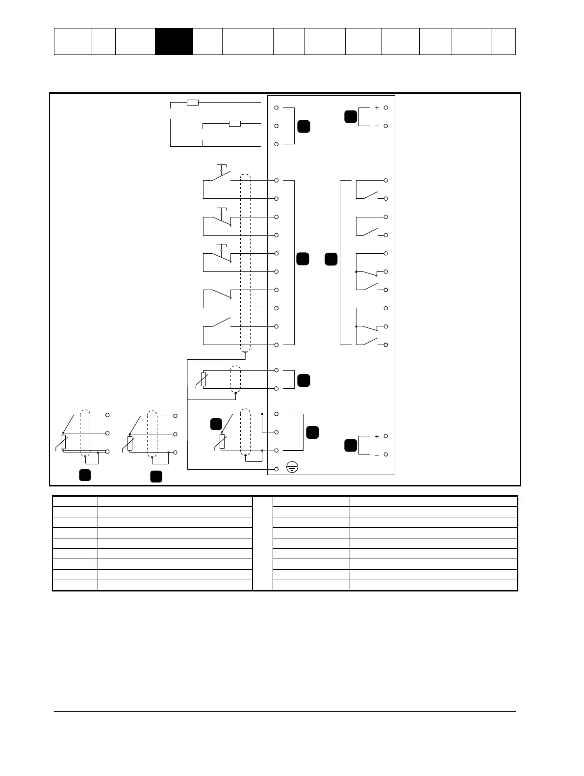
Figure 4-6 Digistart IS electrical schematic
08347.A
5
4
3
2
1
RLC3
COM3
COM1
RLO1
+24V
0V
RLO2
COM2
RLO3
AO1
0V
COM4
RLC4
RLO4
TH2
TH1
DI2
+24V
DI3
+24V
DI4
+24V
+24V
+24V
DI5
PT4
PT5
PT3
CSR
CSL
CSH
DI1
+10%
-15%
+10%
-15%
A
PT4
PT5
PT3
C
PT4
PT5
PT3
BB
E
7
6
220-440 VAC
110-210 VAC
The Digistart IS can be commanded to emergency stop the motor, ignoring the soft stop mode set in Pr 2H.
When the circuit across DI4, +24V is opened, the soft starter allows the motor to coast to stop.
To use the emergency stop function, set Pr 3A to 'Emergency Stop' (this is the default setting).
If emergency stop is not required, change the setting of Pr 3A or connect a link across DI4, +24V.
For keypad control, the soft starter requires:
control supply connections (terminals CSH, CSL, CSR depending on the control voltage)
programmable input A (DI4, +24V) must be closed or Pr 3A Input A Function must be changed from Emergency Stop
 Loading...


