Quick Start
Commissioning
20 Digistart IS User Guide
www.controltechniques.com Issue: 4
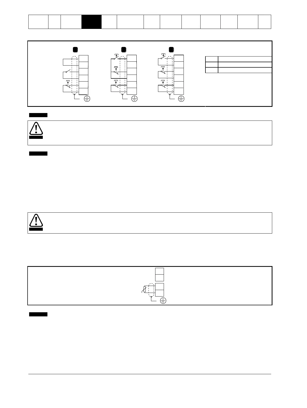
Figure 4-4 Control wiring options
1 2 3
+24V
DI2
+24V
DI1
+24V
DI3
E E E
+24V
DI2
+24V
DI1
+24V
DI3
+24V
DI2
+24V
DI1
+24V
DI3
08340.A
Start/stop
Reset
Start
Stop
Reset
Start
Stop
Reset
For comprehensive information on control connection, see Control connections on page 21.
Do not apply voltage to the control input terminals. These are active 24 Vdc inputs and must be controlled with potential
free contacts.
Cables to the control inputs must be segregated from mains voltage and motor cabling.
You can set the Reset input to either NO or NC (default). See Pr 3N Remote Reset Logic.
4.1.5 Relay outputs
The Digistart IS provides four relay outputs, one fixed and three programmable.
The Run output closes when the soft start is complete (when the starting current falls below 120% of the programmed motor full load
current) and remains closed until the beginning of a stop (either soft stop or coast to stop).
Operation of the programmable outputs is determined by the settings of Pr 4A to 4I.
If assigned to Main Contactor, the output activates as soon as the soft starter receives a start command and remains
active while the soft starter is controlling the motor (until the motor starts a coast to stop, or until the end of a soft stop).
If assigned to a trip function, the output activates when a trip occurs.
If assigned to a flag, the output activates when the specified flag is active (Pr 7A to 7C).
Some electronic contactor coils are not suitable for direct switching with PCB mount relays. Consult the contactor
manufacturer/supplier to confirm suitability.
Three additional outputs are available on the input/output expansion card.
4.1.6 Motor thermistors
Motor thermistors can be connected directly to the Digistart IS. The soft starter will trip when the resistance of the thermistor circuit
exceeds approximately 3.6 kor falls below 20 .
Figure 4-5 Motor thermistor connection
No motor thermistors
Motor thermistors
If no motor thermistors are connected to the Digistart IS thermistor input terminals TH1, TH2 must be open. If TH1, TH2
are shorted, the Digistart IS will trip.
The thermistor circuit should be run in screened cable and must be electrically isolated from ground and all other power
and control circuits.
4.1.7 Programmable inputs
The default setting of programmable input A is 'Emergency Stop' (Pr 3A). If emergency stop is not required, change the setting
of Pr 3A or connect a link across DI4, +24V.
If programmable input A is set to 'Emergency Stop', an open circuit across DI4, +24V will initiate an emergency stop. The soft starter
will allow the motor to coast to stop, ignoring the soft stop mode set in Pr 2H.
 Loading...


