Quick Start
Commissioning
Digistart IS User Guide 19
Issue: 4 www.controltechniques.com
Tighten the cables as follows:
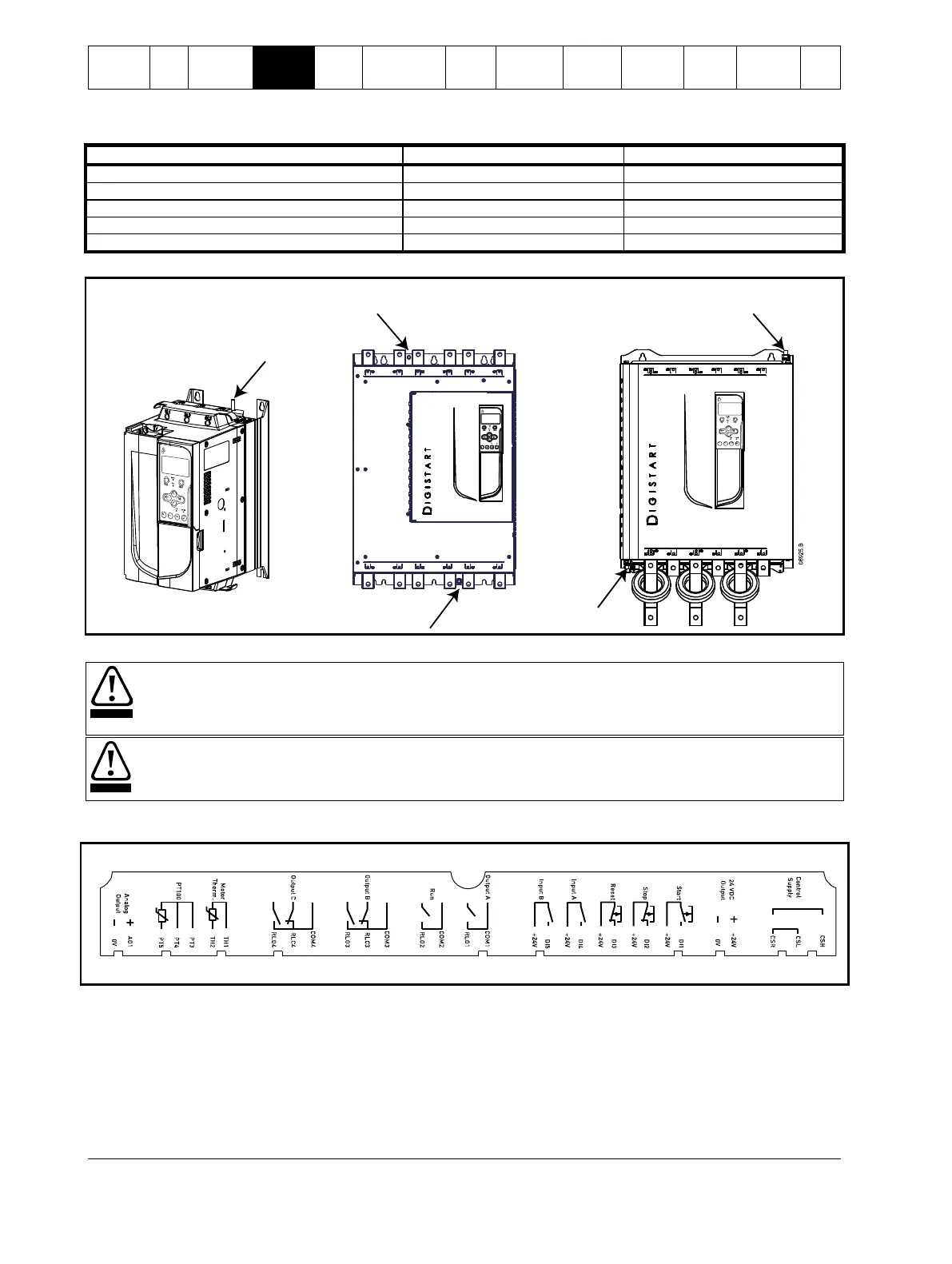
Table 4-1 Ground terminal maximum torque settings
Figure 4-2 Ground terminal locations
IS2x0145B to IS2x0220B and IS3x0255N to
IS561600N
4.1.3 Control terminals
Always connect control voltage to the correct terminals:
110 to 210 Vac: CSL-CSR or
220 to 440 Vac: CSH-CSR
The installer must ensure that the external control circuits are insulated from human contact by at least one layer of
insulation (supplementary insulation) rated for use at the AC supply voltage.
Control terminations use 2.5mm
2
plug-in terminal blocks. Unplug each block, complete the wiring, then reinsert the block.
Figure 4-3 Control terminal layout
08339.A
220~440 VAC
110~ 210 VAC
4.1.4 Start/Stop control logic
The Digistart IS has three fixed inputs for remote control. These inputs should be controlled by contacts rated for low voltage, low
current operation (gold flash or similar).
The maximum cable run is determined by the type of cable used, provided the maximum resistance of this cable does not exceed
100 Ohms. The cables must be twisted in pairs and shielded. The shield must be grounded at one end only, that is, at the soft
starter end. To avoid any EMC disturbance from the motor power cables, the thermistor cable must be separated from the motor
power cables by a minimum parallel distance of 300 mm.
 Loading...


