1592001830 XC645D GB r3.4 04.09.2017.docx XC645D 19/50
oA2 (term. 7-8), oA3 (term. 9-10), oA4 (term. 11-12), outputs 2 3 4 configuration: by means
of these parameters the plant can be dimensioned according to the number and type of
compressors and/or fans and the number of steps for each one.
Each relay according to the configuration of the oA(i), where (i) = 1, 2, 3, 4, parameter can
work as:
- Not used: oA(i) = nu
- Compressor circuit1: oA(i) = cPr1,
- Step: oA(i) = StP
- Digital Scroll or Stream: oA(i) = dGS
- Blocked suction valve of Stream 6D: oA(i) = 6dG
- Fan: oA(i) = FAn
- Fan with inverter/ECI fan: oA(i) = InF
- Alarm: oA(i) = ALr
- Injection of cooling liquid: oA(i) = Lin
- Flood protection function: oA(i) = Liq
- Valve for hot gas injection in case of low superheat: oA(i) = HGi
NOTE: also the “cPr2”, “InC1”, “InC2”, “dGst” ” values are present. These values must not
be used..
According to the oA1, oA2, oA3, oA4 configuration, 2 kinds of plant can be defined:
Rack with compressors only: all the oAi different from FAn
Rack with compressors and fans: both FAn and CPr are used for oAi.
NOTE: COMPRESSOR WITH STEPS CONFIGURATION: the output of compressor has to be
set before the output of the step.
ES. Compressor with 1 step: oA2 = cPr, oA3= StP.
If an oA(i) set as step without any previous oAi set as cPr the configuration alarm “CStP”
will be activated.
PLANT CONFIGURATION EXEMPLES:

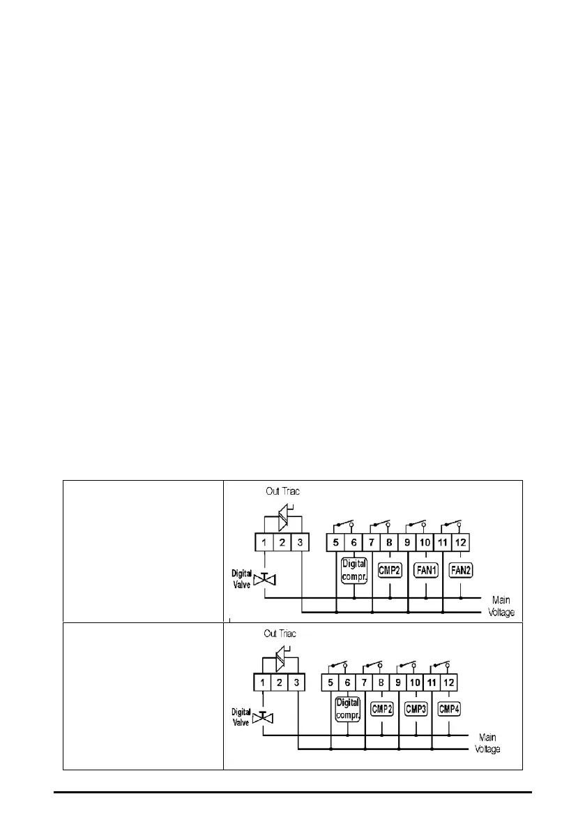 Loading...