EC2-552_65098_EN_R05.docxx replacement for R04 2 / 4 PCN: 864923 30.07.2012
EC2-552 Condensing Unit Controller
Operating Instructions
GB
Set-up and Parameter Modification Using The Keypad
For convenience, an infrared receiver for the optional IR remote control unit is
build-in, enabling quick and easy modification of the system parameters when a
computer interface is not available.
Alternatively, the parameters can be accessed via the 4-button keypad. The
configuration parameters are protected by a numerical password. The default
password is “12”. To select the parameter configuration:
• Press the PRG button for more than 5 seconds
• A flashing 0 is displayed
• Press or until 12 is displayed; (password)
• Press SEL to confirm password
• The first modifiable parameter code is displayed (/1).
• To modify parameters see "Parameter Modification" below.
Parameter Modification: Procedure
• Press or to show the code of the parameter that has to be changed;
• Press SEL to display the selected parameter value;
• Press or to increase or decrease the value;
• Press SEL to temporarily confirm the new value and display its code;
Repeat the procedure from the beginning "press or to show..."
To exit and save the new settings:
Press PRG to confirm the new values and exit the parameters modification
procedure.
To exit without modifying any parameter:
• Do not press any button for at least 60 seconds (TIME OUT).
• Press “ESC” on IR remote control.
Temporary Display Of Data:
It is possible to temporarily display the values of the different sensors. This is a
useful feature when initially setting-up the system without the aid of the
WebPages. Press the SEL sequentially. The value displayed on the screen
corresponds to the number corresponding to the /1 parameter. Action only valid
when parameter H2 = 3
Load Default Parameters:
The default parameter settings can be reloaded into the controller memory by using
the special function described below
Special Functions:
The Special Functions can be activated by:
• Press and together for more than 5 seconds.
A flashing 0 is displayed.
• Press or until the password is displayed (default = 12). If password was
changed, select the new password.
• Press SEL to confirm password
A 0 is displayed and the Special Function mode is activated.
• Press or to select the function. The number of special functions is
dynamic and controller dependent. See list below.
• Press SEL to activate the function without leaving the special function mode.
• Press PRG to activate the function and leave the special function mode.
Most of the Special Functions work in a toggle mode, the first call activates the
function, and the second call deactivates the function.
The indication of the function can only be displayed after exiting the special
function mode.
• 0: Display test function
• 1: Displays the current TCP/IP address
• 2: Set the controller TCP/IP address to the default value: 192.168.1.101
• 3: Resets all parameters to the factory default setting. The controller will
indicate “oF” during the reset.
The data to be shown on the display can be selected by the user. In case of an alarm, the
alarm code is displayed alternately with the selected data. The user can inhibit the alarm
code. Press the SEL button to scroll through all possible displayable data.
The display will show for one second the numerical identifier of the data and then the
selected data. After two minutes the display will return to the by parameter /1 selected
data.
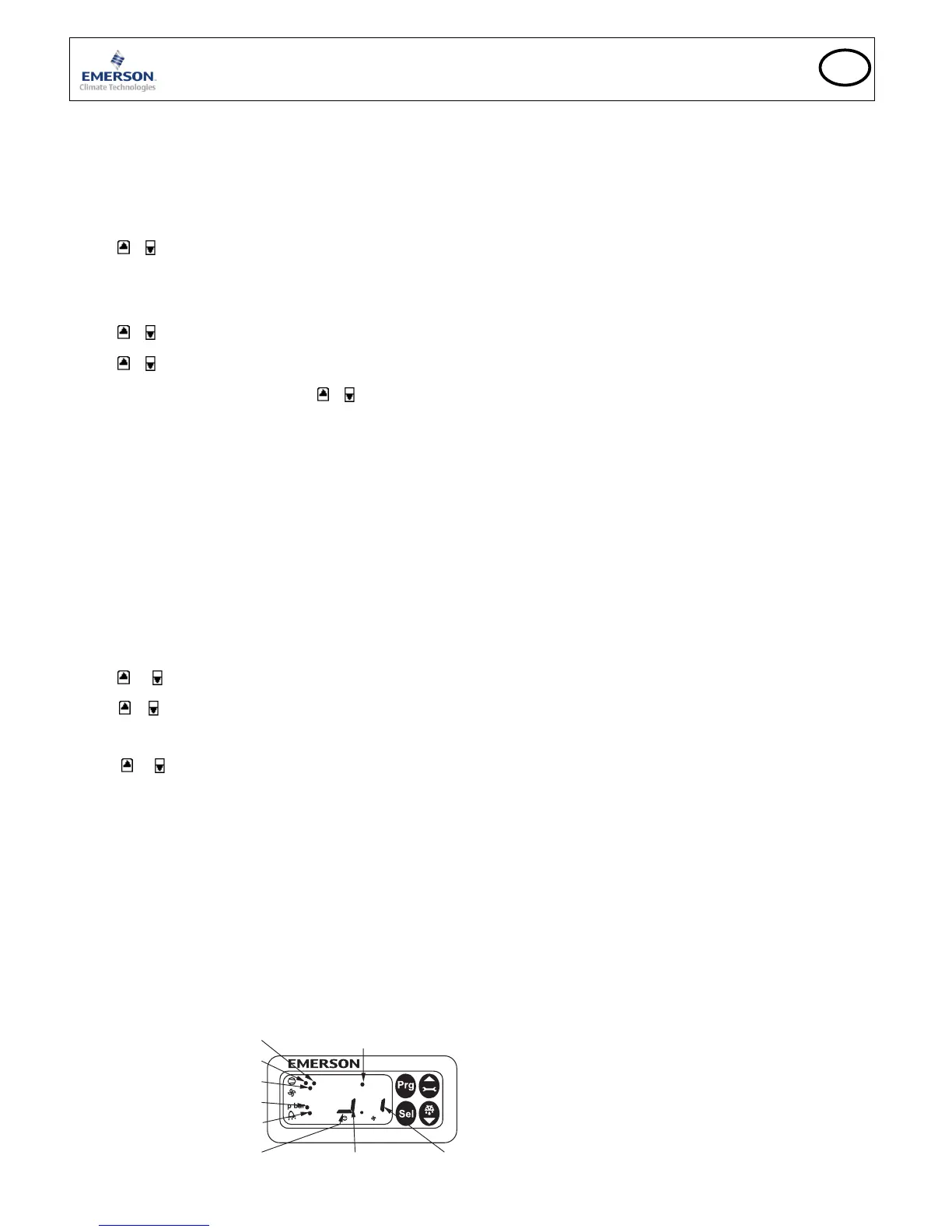
Display indicates suction side -
IR LED
Compressor 1 on Fan on
Indications On The Display:
Compressor Controller
• State
• Alarm in combination with alarm message and alarm LED
• Suction pressure or saturation temperature from suction pressure
• Parameter
Condenser fan controller
• State
• Alarm in combination with alarm message and alarm LED
• Condensing pressure or saturation temperature from condensing pressure
• Parameter
Other display
• Pressure: Pressure value in bar (g)
• Alarm: Alarm condition
• IR: IR communication enabled
Alarm Codes
hP High pressure alarm
Controller 1: suction pressure higher than the maximum limit
Controller 2: condensing pressure higher than the maximum limit
lP Low pressure alarm
Controller 1: suction pressure lower than the minimum limit
Controller 2: condensing pressure lower than the minimum limit
d1 Discharge temperature alarm
Digital scroll only: Discharge end temperature is too high
EP Error pressure
Controller 1: suction pressure sensor failure
Controller 2: condensing pressure sensor failure
Fr Fast recovery alarm
Controller 1: fast recovery from low suction pressure
Controller 2: fast recovery from low condensing pressure
hr High discharge pressure alarm
Controller 1: high discharge pressure recovery
Controller 2: high discharge pressure recovery
rE Emergency run
Controller 1: runs with c6 numbers of compressors
Controller 2: runs with c6 numbers of fans
E1 Feedback alarm 1
Controller 1: digital input associated with compressor 1 has changed into
alarm state (safety chain)
Controller 2: digital input associated with fan(s) has changed into alarm state
(safety chain)
E2 Feedback alarm 2
Controller 1: digital input associated with compressor 2 has changed into
alarm state (safety chain)
n1 Service alarm 1
Controller 1: compressor 1 operating time higher than run limit (A9)
Controller 2: fan operating time higher than run limit (A9)
n2 Service alarm 2
Controller 1: compressor 2 operating time higher than run limit (A9)
Er Data error
Data send to the display is out of range
Messages
--- No data to display
The display will show an “---” at node start up and when no data is send to the
display.
In Reset to default values activated
The display will show an “In” when the factory default configuration data set
is initialized.
Id Wink request received
The display will show a flashing “Id” when the wink request was received.
The flashing “Id” will be shown on the display until the service button will be
pressed, or a 30 min delay timer will expire or a second wink request is
received. This function is action only when using SNMP protocol
OF Node is offline
The node is offline and no application is running. This is the result of a
network management command and will happen for example during node
installation.
 Loading...