EC2-552_65098_EN_R05.docxx replacement for R04 3 / 4 PCN: 864923 30.07.2012
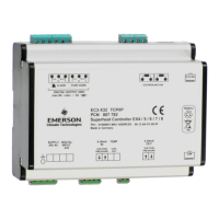
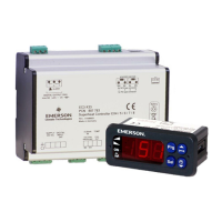
EC2-552 Condensing Unit Controller
Operating Instructions
GB
Controller 1 (Compressor controller)
/ DISPLAY PARAMETERS Min
/1 Value to be shown on display 0 7 - 0
0 = compressors and fans states (controller 1 and 2)
1 = suction pressure (bar)
2 = saturation temperature from suction pressure (°C)
3 = condensing pressure (bar)
4 = saturation temperature from condensing pressure (°C)
5 = Digital Scroll capacity (%)
6 = fan speed (%)
7 = Digital Scroll discharge temperature (°C)
P SET-POINT PARAMETERS - C1
P0 Pressure set-point (suction) for
compressor circuit
-1.0
50 bar 3.0
P1 Pressure band (control band for P/PI,
dead band for dead band control mode)
0.0 50 bar 2.0
P3 Fast recovery from low pressure -9.9
50 bar -9.9
P8 High discharge pressure recovery -9.9
50 bar 50
t TIME PARAMETERS
t1
(1)
Time delay before adding capacity 0 99 10sec 3
t2
(1)
Time delay before removing capacity 0 99 10sec 3
t3
(1)
Compressor minimum on time 0 99 10sec 6
t4
(1)
Compressor minimum off time 0 99 10sec 6
t5 Maximum compressor switching 0 199 1/hr 0
A ALARM PARAMETERS - C1
A2 Minimum suction pressure alarm
limit
-1.0
50 bar 1.0
A3 Maximum suction pressure alarm
limit
-1.0
Delay time for minimum pressure
alarm limit
0 99 10sec 0
A5
(1)
Delay time for maximum pressure
alarm limit
0 99 10sec 0
A6 High discharge temperature cut-out
cut-in = cut-out – 10°C
100
Compressor serial alarm delay 0 99 10sec 0
A9
(2)
Compressor run limit 0 99
10 000hr
0
u STEP ENABLE PARAMETERS - C1
u0 Reset operating time 0 3 - 0
0 = do nothing
1 = reset operating time compressor 1
2 = reset operating time compressor 2
3 = reset operating time all compressors
u1 Enable/disable compressor 1 0 1 flag 1
u2 Enable/disable compressor 2 0 1 flag 1
c APPLICATION PARAMETERS - C1
c1 Number of compressors 1 2 - 2
c4 Compressor 1 control mode 0 2 - 2
0 = compressor 1 in standard control loop
1 = compressor 1 act as base load compressor
2 = compressor 1 is a digital scroll compressor & base load
c5 Compressor switch logic 0 1 flag 0
0 = FILO logic (First In, Last Out)
Capacity demand: Adds first compressor out of available com-
pressors. (= compressors where min off time (t4) is fulfilled)
Capacity excess: Removes last compressor out of available com-
pressors. (= compressors where min on time (t3) is fulfilled)
1 = Rotation enabled
Capacity demand: Adds compressor with lowest runtime out of
available compressors. (= where min off time (t4) is fulfilled)
Capacity excess: Removes compressor with highest runtimes out
of available compressors. (= where min on time (t3) is fulfilled)
Number of compressors to switch on
in case of sensor failure
0 2 - 0
F MODULATING PARAMETERS -
F2 Minimum output value 10 100 % 20
F3 Maximum output value 10 100 % 100
F6 PWM rate (Digital scroll) 10 20 sec 20
r SENSOR PARAMETERS - C1
r0 Suction pressure sensor minimum
value
-1.0
50 bar -0.8
SENSOR PARAMETERS - C1
(continued)
Min
r1 Suction pressure sensor maximum
value
-1.0 50 bar 7.0
r2 Pressure offset for suction pressure
-1.0 1.0 bar 0.0
r3 Refrigerant type 0 7 - 4
0 = no temperature conversion;
1=R22;2=R134a;3=R507;4=R404A;5=R407C;6=R407A;7=R407F
Controller 2 (Fan controller)
P SET-POINT PARAMETERS -
P0 Pressure set-point (condensing) for
fan circuit
-1.0 50 bar 14.0
P1 Pressure band (control band for
P/PI, dead band for dead band
control mode)
0.0 50 bar 4.0
A
ALARM PARAMETERS - C2
A2 Minimum condensing pressure
alarm limit
-1.0 50 bar 10.0
A3 Maximum condensing pressure
alarm limit
-1.0 50 bar 27
A4
(1)
Delay time for minimum pressure
alarm limit
0 99 10sec 0
A5
(1)
Delay time for maximum pressure
alarm limit
0 99 10sec 0
A9
(2)
0
u STEP ENABLE PARAMETERS - C2
u0 Reset operating time
0 = do nothing
1 = reset operating time fan 1
0 1 - 0
u1 Enable/disable fan 1 0 1 flag 1
c
APPLICATION PARAMETERS - C2
c2 Fan controller operation
0 = disabled
1 = enabled
0 1 - 1
c6 Fan behaviour on in case of sensor
failure
0 = Analog output 0% (0 V)
1 = Analog output 100% (10 V)
0 1 - 0
F
MODULATING PARAMETERS -
F2 Minimum output value 0 100 % 0
F3 Maximum output value 0 100 % 100
r
SENSOR PARAMETERS - C2
r0 Condensing pressure sensor
minimum value
-1.0 50 bar 0.0
r1 Condensing pressure sensor
maximum value
-1.0 50 bar 30
r2 Pressure offset for condensing
pressure
-1.0 1.0 bar 0.0
H OTHER PARAMETERS
H2 Keyboard and IR remote control 0 3 - 3
0 = all disabled
(Caution, access to controller only via network possible)
1 = Keyboard enabled
2 = IR remote control enabled
3 = Keyboard and IR remote control enabled
H3 IR remote control access code 0 199 - 0
H5 Password 0 199 - 12
(1)
Shown value x 10 = Time in seconds. Ex. a value of 2 means 20 seconds.
(2)
Shown value x 10 000 = Time in hours. Ex. a value of 2 means 20.000 hours.
 Loading...

