OI_EC2-XC645CX_A1_A2L_A3_EN_Rev01_866933.docx EC2-XC645CX 37/54
18.3 Condenser with Inverter or Ec Fans–Analog Output Setting
This configuration is used when all fans of the condensing group are ECI fans or driven by one
inverter or a chopped phase driver.
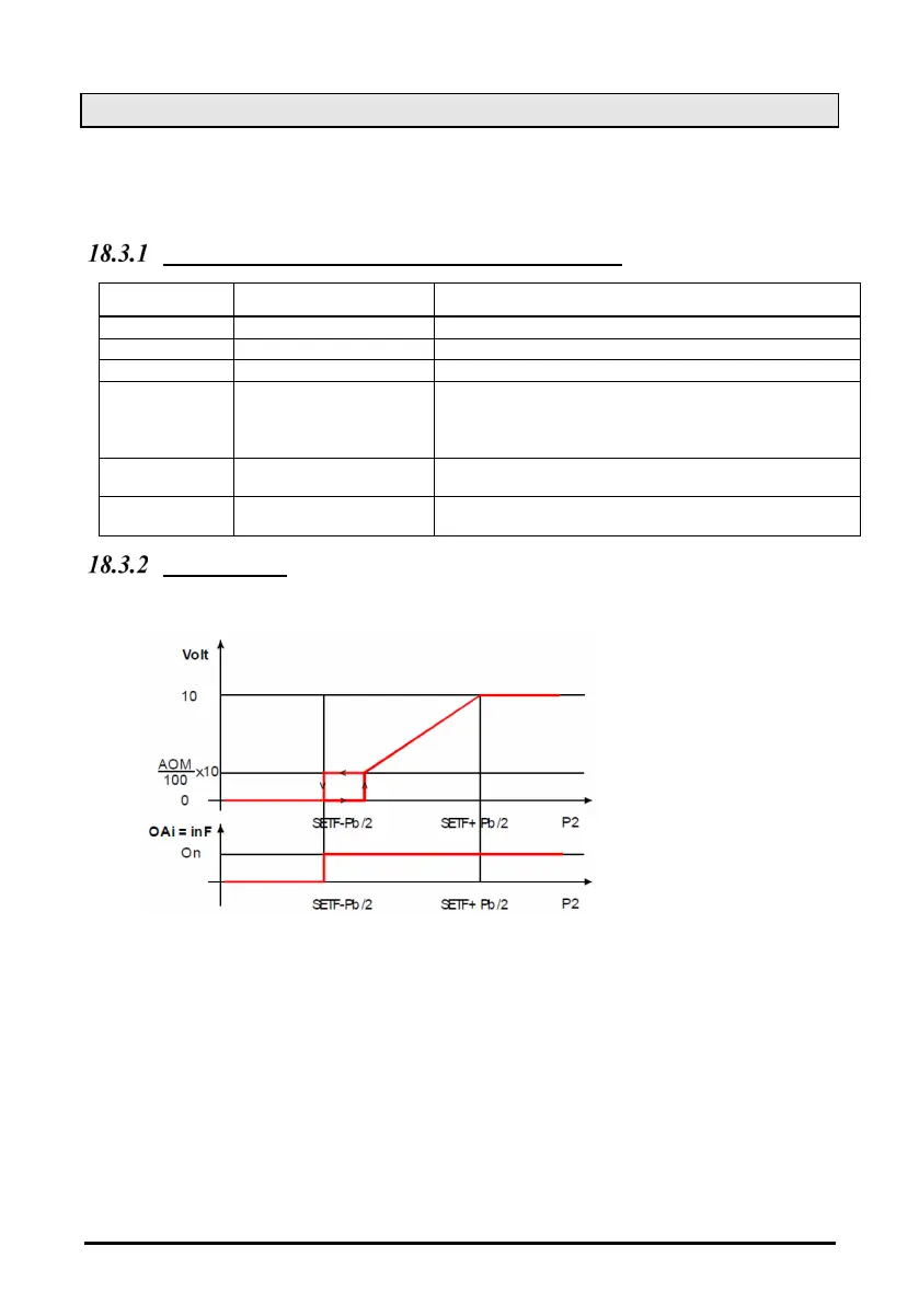
The capacity used by the inverter is proportional to the delivery pressure value inside the
regulation band (SETF-Pb/2 - SETF+Pb/2).
Condenser fan configurations and parameters
PARAMETER DESCRIPTION ACTION
One relay is used to enable the action of the inverter.
Set the output as 0 – 10 V
Set the output to drive ECI or inverter fan
analog output
The minimum voltage is 0 V.
NOTE: Verify on the inverter of ECI fan of chopped
phase driver that with this input a proper
output is supplied to the fan.
Time of analog output
at max after the start
To start the fan the controller supplies 10 V output for
5 s, then starts standard regulation
Maximum % variation
per minute
The analog output takes 1 min to move from the min to
the maximum
How to set it
Parameters involved: oA(i) = inF; AoC = tEn, AoP = P2, AOM = 30, MPM = 100
a. If required, set a relay to drive the invert (is used to signal to the inverter to start and stop the
regulation), by setting:
oA(i) = inF inverter for fans
b. Set the kind of signal of the analog output current (4 - 20 mA) or voltage (0 - 10 V) by the
Analog output setting parameter “AoC”: tEn = 0 - 10 V output; cUr = 4 - 20 mA output
c. Set the function of the analog output:
AoF = InF
d.
Set the time of the analog output at max after start up EI: Aot = 3 s
e.
Set the max % variation per min (MP)
f. At last set also the percentage of analog output in case of probe failure: (0 - 100%) SAO