OI_EC2-XC645CX_A1_A2L_A3_EN_Rev01_866933.docx EC2-XC645CX 38/54
18.4 Analog output “free”
This setting is used to link the analog output 1 to a temperature probe. The analog output will take
values proportional to the temperatures detected by the probe P3 or P4, according to the setting.
Analog output “free” configurations and parameters
PARAMETER DESCRIPTION ACTION
Set the output as 0 - 10 V.
Set the output to drive for instance a de-
superheater.
Reference probe for the analog
output 1 (used only if AOP =
It’s possible to set only P3 or P4 probes.
P3 must be set as temperature probe:
P3C = nt10 (NTC 10 K) or nt86 (NTC 86 K)
Temperature value associated
to minimum value of analog
It’s the start scale of the analog output.
Temperature value associated
to the maximum value of analog
It’s the end scale of the analog output.
output
The minimum voltage is 0 V.
NOTE: Verify on the inverter of ECI fan of
chopped phase driver that with this
input a proper output is supplied to
Time of analog output at max
after the start
With AOt = 5 the controller supplies 10 V
output for 5 s at fan start, then starts
Maximum % variation per
minute
The analog output takes 1 min to move from
the min to the maximum.
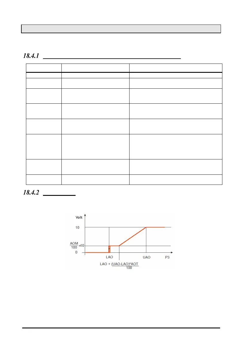
How to set it
Parameters involved: AoC = tEn, AoF = FrE, AOP = P3: LAO = 20; UAO = 40; Aot = 0,
AOM = 30, MPM = 100
a. Set the kind of signal of the analog output current (4 – 20 mA) or voltage (0 – 10 V) by the
Analog output setting parameter “AoC”: tEn = 0 – 10 V output; cUr = 4 - 20 mA output
b. Set the function of the analog output:
AoF = FrE
c.
Set the time of the analog output at max after start up EI: Aot = 3s
d.
Set the start scale temperature by LAO parameter, at which correspond the AOM value of
analog output
e.
Set the end scale temperature by UAO parameter, at which correspond the maximum value
of analog output
f.
Set the max % variation per min (MPM)
g. At last set also the percentage of analog output in case of probe failure: (0 – 100 %) SAO