EasyManua.ls Logo

Emerson Fisher 4200 Series User Manual

Emerson Fisher 4200 Series
44 pages
To Next Page IconTo Next Page
Page #1 background imageLoading...
Page #1 background image
www.Fisher.com
D200354X012
4200 Series Electronic Position
Transmitters
Contents
Introduction 1. . . . . . . . . . . . . . . . . . . . . . . . . . . . . . .
Scope of Manual 1. . . . . . . . . . . . . . . . . . . . . . . . .
Description 2. . . . . . . . . . . . . . . . . . . . . . . . . . . . . .
Specifications 2. . . . . . . . . . . . . . . . . . . . . . . . . . . .
Educational Services 4. . . . . . . . . . . . . . . . . . . . . .
Installation 6. . . . . . . . . . . . . . . . . . . . . . . . . . . . . . . .
Mechanical Connections 7. . . . . . . . . . . . . . . . . . .
Sliding-Stem Actuator Mounting 7. . . . . . . . . . .
Rotary-Shaft Actuator Mounting 7. . . . . . . . . . .
Long Stroke Sliding-Stem Actuator
Mounting Type 585C and 470-16 8. . . . . . . .
Long Stroke Sliding-Stem Actuator
Mounting Type 585CLS and 490 9. . . . . . . .
Electrical Connections 9. . . . . . . . . . . . . . . . . . . . .
Conduit 9. . . . . . . . . . . . . . . . . . . . . . . . . . . . . . . .
Field Wiring 9. . . . . . . . . . . . . . . . . . . . . . . . . . . . .
Potentiometer Alignment 12. . . . . . . . . . . . . . . . .
Direct or Reverse Action 14. . . . . . . . . . . . . . . . . .
Operating Information 16. . . . . . . . . . . . . . . . . . . . .
Initial Considerations 16. . . . . . . . . . . . . . . . . . . . .
Transmitter and Position Switch
Conditions 16. . . . . . . . . . . . . . . . . . . . . . . . . .
Normal Operation 16. . . . . . . . . . . . . . . . . . . . . . . .
Calibration 17. . . . . . . . . . . . . . . . . . . . . . . . . . . . . . .
Test Equipment Required 17. . . . . . . . . . . . . . . . .
Test Connections to the Field Wiring
Compartment 17. . . . . . . . . . . . . . . . . . . . . . . . .
Transmitter Circuit Zero and Span
Adjustment 17. . . . . . . . . . . . . . . . . . . . . . . . . . .
High and Low Position Switch Adjustment 19. .
Setting the High Position Switch 19. . . . . . . . . .
Setting the High Position Switch
Deadband 19. . . . . . . . . . . . . . . . . . . . . . . . . . .
Setting the Low Position Switch 19. . . . . . . . . .
Setting the Low Position Switch
Deadband 20. . . . . . . . . . . . . . . . . . . . . . . . . . .
Position Switch Circuit Shutoff 20. . . . . . . . . . . . .
Principle of Operation 21. . . . . . . . . . . . . . . . . . . . .
Transmitter Circuit 21. . . . . . . . . . . . . . . . . . . . . . .
Position Switch Circuit 21. . . . . . . . . . . . . . . . . . . .
Maintenance 22. . . . . . . . . . . . . . . . . . . . . . . . . . . . .
Troubleshooting Procedures 23. . . . . . . . . . . . . .
Transmitter Circuit 23. . . . . . . . . . . . . . . . . . . . . .
Position Switch Circuit 23. . . . . . . . . . . . . . . . . .
W4273-1
SLIDING-STEM
ACTUATOR MOUNTING
W4274-1
ROTARY
ACTUATOR MOUNTING
Figure 1. Typical 4200 Series Position Transmitters
Parts Ordering 26. . . . . . . . . . . . . . . . . . . . . . . . . . . .
Parts List 27. . . . . . . . . . . . . . . . . . . . . . . . . . . . . . . .
Loop Schematics and Nameplates 40. . . . . . . . . .
Introduction
Scope of Manual
This instruction manual provides installation,
operating, calibration, maintenance, and parts
ordering information for the 4200 Series electronic
position transmitters (figure 1). Refer to separate
instruction manuals for information on the actuator
and valve.
Instruction Manual
Form 5596
July 2005
4200 Series Transmitters

Questions and Answers:

Emerson Fisher 4200 Series Specifications

General IconGeneral
BrandEmerson
ModelFisher 4200 Series
CategoryTransmitter
LanguageEnglish

Summary

Introduction

Scope of Manual

Outlines the manual's coverage of installation, operation, calibration, and maintenance.

Description

Product Overview

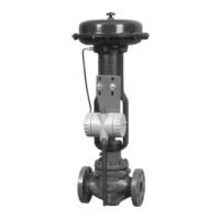
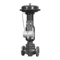
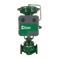
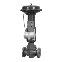
Explains the 4200 Series transmitters' features, applications, and types.

Specifications

Technical Data

Details operating influences, conditions, mounting, electrical classification, and housing.

Installation

Mechanical Connections

Procedures for connecting the transmitter to various actuator types.

Electrical Connections

Instructions for wiring the transmitter, including conduit and field wiring.

Potentiometer Alignment

Procedure to adjust the potentiometer to the center of its electrical travel.

Operating Information

Initial Considerations

Factory calibration details and separate ordering considerations.

Transmitter and Position Switch Conditions

How transmitter and position switches obtain stem position and provide outputs.

Normal Operation

Post-calibration operation and monitoring of output.

Calibration

Test Equipment Required

Lists necessary equipment for calibration and maintenance.

Test Connections to the Field Wiring Compartment

Details on setting up connections for calibration.

Transmitter Circuit Zero and Span Adjustment

Procedure to adjust zero and span for 4-20mA output.

High and Low Position Switch Adjustment

Setting the High Position Switch

Procedure to set the high position switch trip point.

Setting the High Position Switch Deadband

Procedure to adjust the deadband for the high position switch.

Setting the Low Position Switch

Procedure to set the low position switch trip point.

Setting the Low Position Switch Deadband

Procedure to adjust the deadband for the low position switch.

Position Switch Circuit Shutoff

How to shut off position switch circuit capabilities.

Principle of Operation

Transmitter Circuit

Explains the electronic operation of the transmitter circuit.

Position Switch Circuit

Explains the operation of the position switch circuit and relays.

Maintenance

General Maintenance Precautions

Safety warnings and general guidance for maintenance operations.

Troubleshooting Procedures

Transmitter Circuit Troubleshooting

Troubleshooting steps for the transmitter circuit.

Position Switch Circuit Troubleshooting

Troubleshooting steps for the position switch circuit.

Printed Wiring Board Removal and Replacement

Procedures for removing and replacing printed wiring boards.

Parts Ordering

Parts List

Comprehensive list of transmitter common parts and mounting parts.

Loop Schematics and Nameplates

CSA Schematics and Approval Nameplates

Loop schematics and CSA approval nameplates for intrinsic safety.

FM Schematics and Approval Nameplates

FM schematics and approval nameplates for intrinsic safety and explosion proof.

Related product manuals