Type 6492HM Safety Override System
Refer to Figure 3. Once placed in operation, the
upstream Type 92B (B) pilot senses the intermediate
pressure between both valves, and the Type 6492HM
(A) pilot senses downstream pressure of the second
valve. As demand for ow increases, intermediate
pressure will fall causing the Type 92B pilot to open. As
the Type 92B pilot opens, loading pressure to the main
valve increases, opening the main valve.
The Type 6492HM (A) safety override pilot remains
open because its setpoint is above the setpoint of
the downstream valve. In the unlikely event that the
downstream valve fails open, downstream pressure
will rise above the downstream valve’s setpoint. This
pressure is sensed by the Type 6492HM (A) safety
override pilot. As downstream pressure increases
the Type 6492HM (A) safety override pilot closes,
reducing loading pressure to the upstream main valve,
which positions the main valve to maintain desired
downstream override pressure.
In the event that the upstream valve fails, the
downstream valve will prevent downstream pressure
from rising above safe operating levels.
It is recommended to install some type of warning
system, such as a sentinal relief valve, to warn the
operator that a valve has failed in the system. This
will prevent prolonged operation with one valve, which
could cause valve trim wear and noise associated with
operation at high dierential pressures.
Installation
!
WARNING
Regulators should be installed, operated
and maintained in accordance with
federal, state and local codes, rules and
regulations and Emerson instructions.
If the regulator vents steam or a leak
develops in the system, it indicates that
service is required.
Failure to take the regulator out of
service immediately may create a
hazardous condition.
Call a service man in case of trouble.
Only a qualied person must install or
service the regulator.
CAUTION
Be sure to install Type 92B pilot above
the pipeline with the adjusting screw
pointing up and the control line sloped
at a downward pitch to the main line to
ensure proper condensate drainage.
The following points should be kept in mind when
installing this pressure reducing valve. See Figure 4
for a schematic drawing of a typical installation.
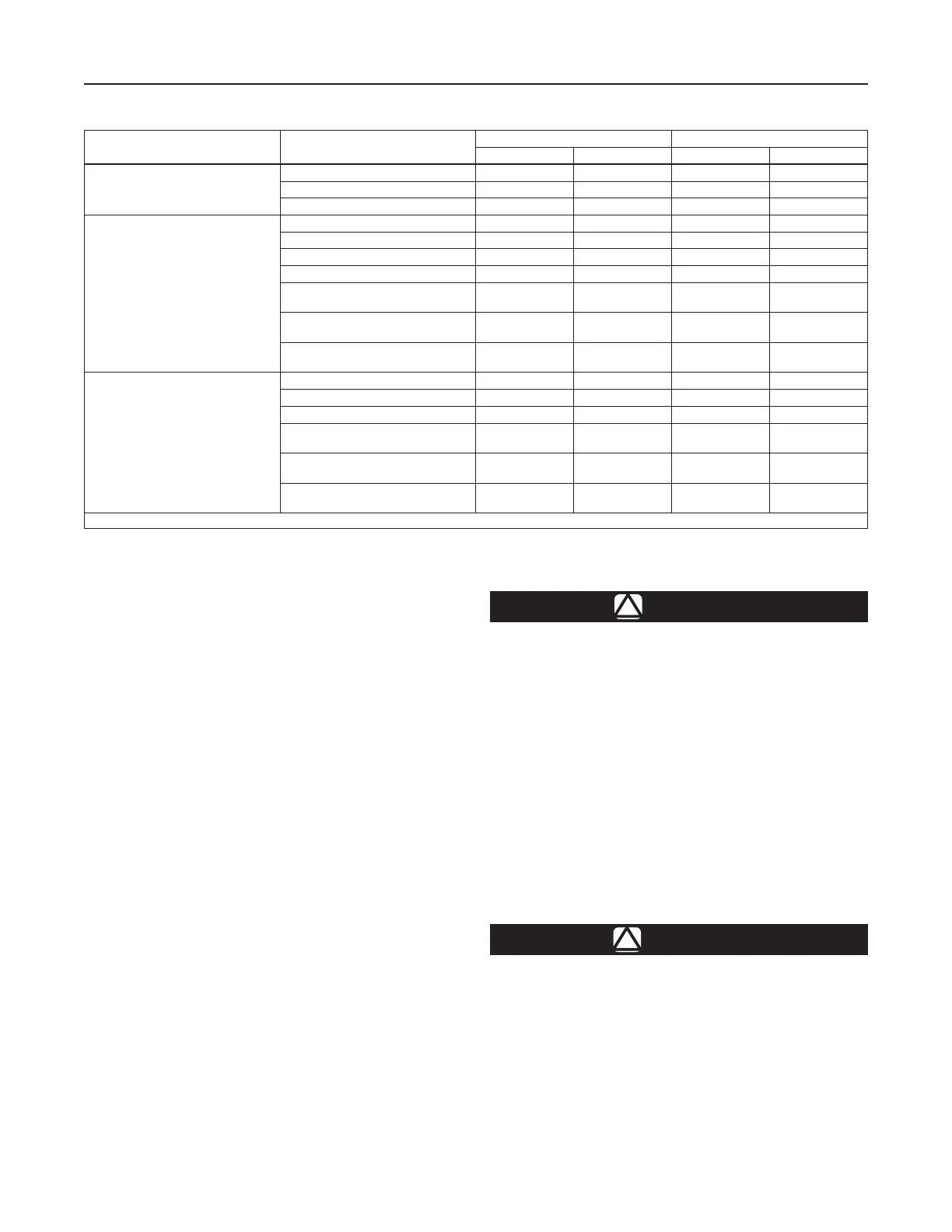
Table 3. Maximum Inlet Pressures and Temperatures
BODY MATERIAL END CONNECTION
MAXIMUM INLET PRESSURE MAXIMUM TEMPERATURE
psig bar °F °C
Cast Iron
NPT 250 17.2 406 208
CL125 FF 125 8.6 353 178
CL250 RF 250 17.2 406 208
Steel
NPT 300 20.7 450 232
SWE 300 20.7 450 232
CL150 RF 185 12.8 450 232
CL300 RF 300 20.7 600 316
(1)
PN 16/25/40 (NPS 1, 1-1/2, 2 and 3 /
DN 25, 40, 50 and 80)
300 20.7 600 316
(1)
PN 16 (NPS 4 / DN 100) 185 12.8 450 232
PN 25/40 (NPS 4 / DN 100) 300 20.7 600 316
(1)
Stainless steel
NPT 300 20.7 450 232
CL150 RF 175 12.1 450 232
CL300 RF 300 20.7 600 316
(1)
PN 16/25/40 (NPS 1, 1-1/2, 2 and 3 /
DN 25, 40, 50 and 80)
300 20.7 600 316
(1)
PN 16
(NPS 3 and 4 / DN 80 and 100)
175 12.1 450 232
PN 25/40
(NPS 3 and 4 / DN 80 and 100)
300 20.7 600 316
(1)
1. 450°F / 232°C with standard seat ring, 600°F / 316°C with seal weld option.
4
Type 92B

 Loading...


