Do you have a question about the Emerson Fisher 92B and is the answer not in the manual?
| Brand | Emerson |
|---|---|
| Model | Fisher 92B |
| Category | Control Unit |
| Language | English |
Provides instructions for installation, startup, maintenance, and parts ordering for the Type 92B Valve.
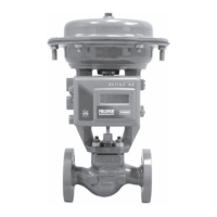
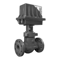
Describes the Type 92B Pressure Reducing Valve as a standard steam valve for industry, used in various applications.
Details the pilot-operated globe-style pressure reducing valve configuration with post guiding and flow-to-close action.
Refers to Table 1 for details on body sizes and various end connection styles available for the valve.
Refers to Table 3 for information on body ratings and maximum allowable inlet pressures.
Specifies the maximum allowable outlet pressure limits for cast iron and steel/stainless steel bodies.
Refers to Table 2 for available outlet pressure ranges based on pilot type and spring selection.
States the minimum differential pressure needed for full valve stroke with different springs.
Specifies that pressure registration is external for the Type 92B valve.
Refers to Table 3 for temperature capabilities of the valve.
Lists the NPT connection sizes for downstream control lines based on body sizes.
Refers to Figure 2 for a schematic illustrating the operational flow of the Type 92B valve.
Explains how the pilot and main valve work together to control downstream pressure based on demand.
Describes the function of the check valve in limiting diaphragm differential pressure and preventing damage.
Explains how the upstream 92B pilot and 6492HM pilot sense pressures and control the main valve.
Describes how the downstream valve handles upstream valve failure to maintain safe operating levels.
Provides critical warnings about installation, operation, and maintenance according to codes and qualified personnel.
Advises on proper control line installation for condensate drainage and to avoid turbulence.
Instructs to inspect for shipment damage and remove foreign materials before installation.
Advises to blow down the pipeline and install a strainer ahead of the Type 92B valve.
Recommends installing block valves for isolation and bypass piping for continuous operation during maintenance.
Specifies mounting the Type 92B with the diaphragm case above the pipeline to prevent condensate collection.
Instructs to install the valve according to the flow direction arrow cast on the body.
Details how to connect the external control line to the Type 92B body tapping based on size.
Shows a schematic for a typical single-stage installation of the Type 92B valve.
Illustrates a typical single-stage parallel installation configuration for the Type 92B valve.
Presents a schematic of a typical two-stage installation using primary and secondary Type 92B valves.
Displays top and side views of the safety override system installation, showing component relationships.
Provides important notes on control line sizing, placement, tapping, and condensate drainage.
Warns about accumulated condensate causing water hammer and potential injury or death.
Details steps for preparing new installations, including blowing down piping and cleaning strainers.
Outlines procedures for preparing older installations, focusing on draining condensate.
Explains how to adjust the pilot's set screw to change the downstream pressure setting.
Provides step-by-step instructions for putting the Type 92B valve into operation after installation or disassembly.
Guides on operating the safety override system, including pilot adjustments and setpoint considerations.
Lists steps for safely taking the regulator out of operation, including closing valves and venting pressure.
Lists potential causes for operating difficulties like improper installation or dirt accumulation.
Suggests checking for plugged bleed fittings or clogged pilot internal parts.
Advises checking for ruptured diaphragms or undersized valves.
Discusses causes like oversizing and suggests reducing gain with a reducing regulator.
Emphasizes isolating the valve and releasing pressure before disassembly.
Provides steps for disassembling the Type 92B main valve, including removing tubing and the diaphragm case.
Details the process of reassembling the Type 92B main valve, including installing the valve plug, flange, and diaphragm assembly.
Outlines steps for disassembling the Type 92B pilot, including removing the valve guide, spring, and stem.
Continues the main valve reassembly with steps for the diaphragm assembly, spring installation, and pilot mounting.
Explains how to remove, inspect, clean, or replace the pilot strainer screen.
Describes how to clear a plugged bleed fitting in the diaphragm case.
Introduces procedures for inspecting, cleaning, or replacing pilot parts for troubleshooting.
Advises to relieve spring compression and remove the pilot before maintenance.
Details disassembly and cleaning of the pilot, including the valve guide, orifice, and plug seating surfaces.
Provides torque values for various fasteners and components of the Type 92B main valve.
Lists torque values for pilot components like valve guide, orifice, and cap screws.
Explains how to order spare parts using the FS or serial number found on the nameplate.
Lists parts for the Type 92B main valve, including part numbers and descriptions.
Continues the parts list for the valve body assembly, covering various end connections and materials.
Lists parts for gaskets and cap screws for different body materials and sizes.
Details parts for the valve plug and springs, including material and pressure drop specifications.
Lists parts for the seat ring and diaphragm head, specifying materials and sizes.
Lists parts for main valves and pilots, including part numbers for diaphragms, fittings, and valve bodies.
Lists mounting parts like pipe nipples, bushings, and connectors for cast iron and steel pilots.
Details parts for optional handwheel and sealed adjusting screw assemblies.
Lists parts for male connectors and elbows used in pilot mounting for different body materials.
Details parts for the pilot valve body, guide, spring, and inner valve for Type 6492HM and 6492HTM pilots.
Lists parts for the orifice, valve stem, bellows retainer, and bellows for the pilots.
Details parts for the diaphragm and lower spring seat for Type 6492HM and 6492HTM pilots.
Displays a diagram of the low-pressure pilot assembly with numbered parts.
Shows a diagram of the high-pressure pilot assembly with numbered parts.
Illustrates the optional handwheel assembly with numbered components.
Displays a diagram of the optional sealed adjusting screw for both steel and cast iron bodies.
Shows a diagram of the cast iron pilot assembly with numbered mounting parts.
Illustrates the steel pilot mounting assembly, specifically the high-pressure pilot.
Displays a diagram of the Type 6492HM pilot assembly with numbered components and lubricant/sealant indications.
Shows the warning label for the safety override pilot, including hazard information and compliance standards.
Lists contact details for Emerson Automation Solutions across different regions.
Contains publication details, copyright information, and legal disclaimers regarding product use.