Instruction Manual
D102748X012
DLC3010 Digital Level Controller
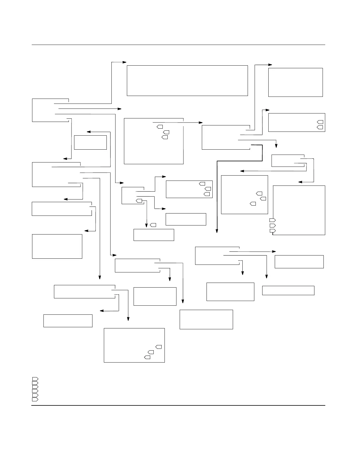
Field Communicator Menu Tree
May 2018
111
NOTES:
1 IN LIQUID LEVEL MODE ONLY
2 IN INTERFACE LEVEL MODE ONLY
3 IN LIQUID DENSITY MODE ONLY
4 ABSENT WHEN PROCESS TEMPERATURE SOURCE IS MANUAL ENTRY
5 ABSENT IN LIQUID DENSITY MODE
6 ABSENT IN LIQUID LEVEL MODE
Service Tools
1 Alerts
2 Variables
3 Trends
4 Maintenance
Alerts
1 No Active Alerts
1 (Visible if there are no active alerts)
1 Refresh Alerts
1 (Visible if an alert is active -- alert name plus description
1 will be visible if the associated alert is active)
3-1
3-3
Maintenance
1 Tests
2 Primary Calibration
3 Secondary Calibration
4 Reset/Restore
Tests
1 LCD Test
2 Loop Test
Reset/Restore
1 Restore Factory Defaults
2 Reset Device
Restore Factory Defaults
1 Restore Factory
Configuration
2 Restore Factory
Compensation
3-4-1
3-4-4
3-4
3
Variables
1 Summary
2 Liquid Level
1
2 Interface Level
2
2 Liquid Density
3
3 Instrument Temperature
4 Process Temperature
5 Analog Output
6 % Range
PV
1 Liquid Level
1
1 Interface Level
2
1 Liquid Density
3
SV
1 Instrument
Temperature
TV
1 Process
Temperature
Primary Calibration
1 Full Calibration
2 Partial Calibration
Full Calibration
1 Min/Max Calibration
2 Two Point Calibration
3 Weight Calibration
Partial Calibration
1 Capture Zero
2 Trim Gain
3 Trim Zero
Analog Output Calibration
1 Analog Output
2 Scaled D/A Trim
Temperature Calibration
1 Instrument Temperature
2 Instr Tmpr Offset
3 Trim Inst Tmpr
4 Process Temperature
4
5 Proc Tmpr Offset
4
62Trim Proc Tmpr
4
Trends
1 PV
2 SV
3 TV
4
Summary
1 Mapped Variables
2 Compensation
3 Signal Tracing
4 Electronics Monitors
Mapped Variables
1 PV
2 SV
3 TV
4 Analog Output
5 % Range
Compensation
1 Comp. Torque Rate
2 Upper Fluid Density
2
3 Lower Fluid Density
5
Signal Tracing
1 Constants
2 Signals
Constants
1 Zero Ref Angle
2 Driver Rod Length
3 Mechanical Gain
4 Displaser Weight
5 Dry Deflection
6 Displacer Volume
7 Reference Buoyancy
8 Displacer Length
9 Level Offset
3-2
Signals
1 Sensor Rotation
2 Rotation Change
3 Buoyant Force
4 Apparent SG
3
5 Preliminary PV
1
6 Scaled PV
5
7 Final PV
Electronics Monitors
1 Input Circuit
2 Processor
3 Writes Remaining
Input Circuit
1 Hall Sensor Signal
2 Hall Drive
Processor
1 Free Time Remaining
Writes Remaining
1 Configuration NVM
2 Transducer NVM
3 Buffer NVM
Secondary Calibration
1 Temperature Calibration
2 Analog Output Calibration
Figure B‐7. Service Tools
3-2-1
3-2-1-1
3-2-1-2
3-2-1-3
3-2-1-3-1
3-2-1-3-2
3-2-1-4
3-2-1-4-1
3-2-1-4-2
3-2-1-4-3
3-4-3
3-4-3-23-4-
3-4-4-1
3-3-1
3-3-2
3-3-3
3-4-2
3-4-3-1
3-4-2-2
3-4-2-1
4
6
5
5

 Loading...


