Instruction Manual
D102748X012
DLC3010 Digital Level Controller
Maintenance & Troubleshooting
May 2018
82
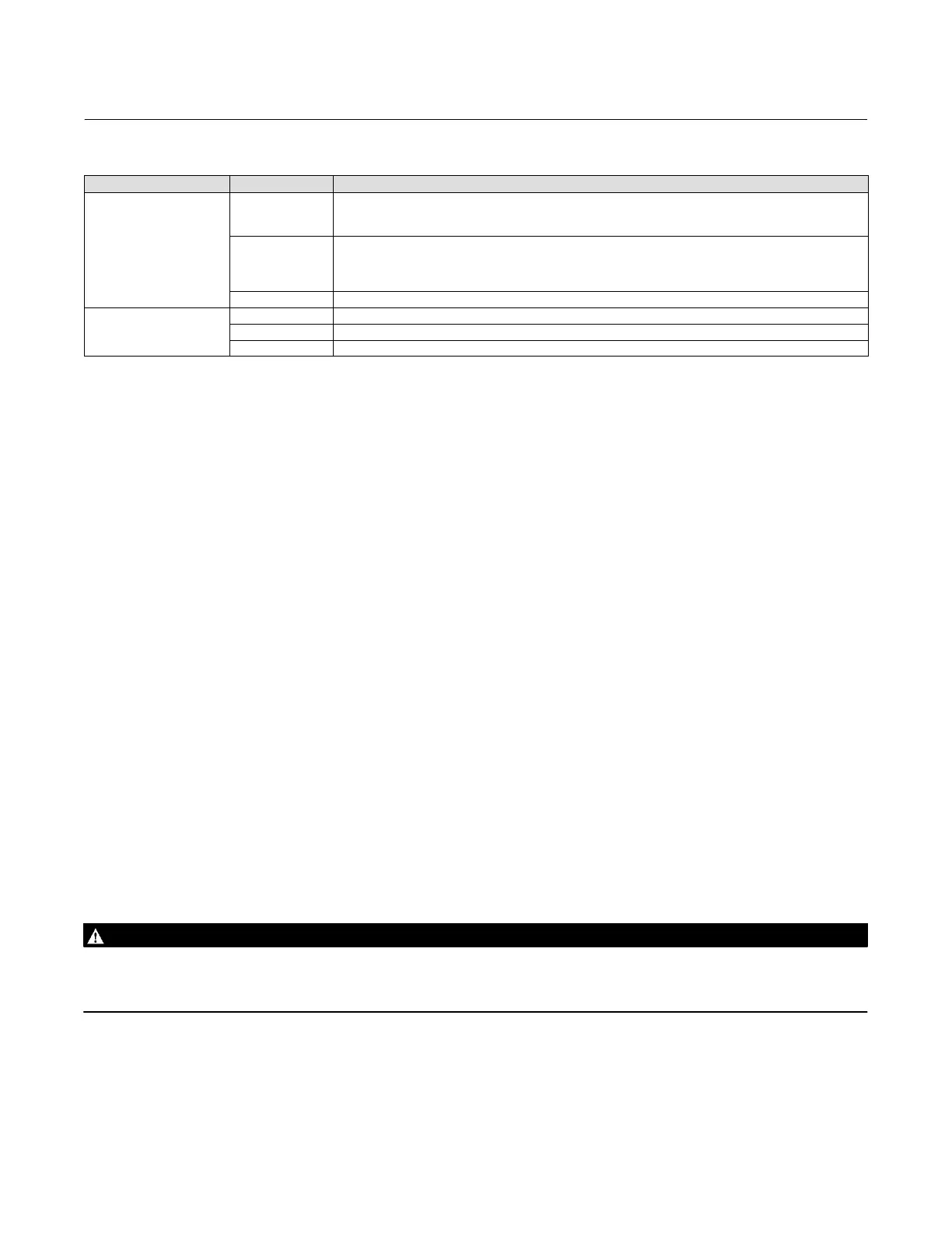
Table 6‐1. Troubleshooting (continued)
Symptom Potential Source Corrective Action
Erratic Output
Loop Wiring
If output current enters a limit cycle between zero and a value within the 4-20 mA range when level reaches some
arbitrary upper threshold,
20. Check for excessive loop resistance or low compliance voltage. (See items 2 and 4 above.)
Transducer Module
If output is very random / noisy as compared to actual process state:
21. Check for possible contamination in the electronics compartment. Clean and dry contacts on connectors.
22. Swap Electronics module with a known-good unit to isolate problem to Transducer or Electronics module.
Replace the module with the problem.
Electronics Module See items 21. and 22. above.
Scrambled or erratic Display
on LCD
Loop Wiring —see item 20 above. (Insufficient voltage to operate display)
LCD Assy 23. Swap LCD Assy with known good part.
Electronics Module 24. Connector solder joint failure in electronics module. Replace module.
Test Terminals
Test connections inside the terminal box can be used to measure loop current. These terminals are across an internal 1
ohm resistor that is in series with the loop.
1. Remove the terminal box cap.
2. Adjust the test meter to measure a range of 0.001 to 0.1 volts.
3. Connect the positive lead of the test meter to the + connection and the negative lead to the T connection inside the
terminal box.
4. Measure Loop current as:
Voltage (on test meter) 1000 = milliamps
example:
Test meter Voltage X 1000 = Loop Milliamps
0.004 X1000 = 4.0 milliamperes
0.020 X 1000 = 20.0 milliamperes
5. Remove test leads and replace the terminal box cover.
Removing the Digital Level Controller from the Sensor
Because of its modular design, most of the service and maintenance to the digital level controller can be done without
removing it from the sensor. However, if necessary to replace sensor to instrument mating parts or parts in the
transducer housing, or to perform bench maintenance, perform the following procedures to remove the digital level
controller from the sensor.
WARNING
On an explosion‐proof instrument, remove the electrical power before removing the instrument covers in a hazardous
area. Personal injury or property damage may result from fire and explosion if power is applied to the instrument with the
covers removed.
Tools Required
Table 6‐2 lists the tools required for maintaining the DLC3010 digital level controller.

 Loading...


